Lesson 08: Synchronous Sequential Logic Circuits
8.1 Sequential Circuits
Sequential circuits are an essential component of digital electronics, playing a crucial role in the design and functionality of various digital systems, ranging from simple devices like digital clocks to complex computing machines like microprocessors. Unlike combinational circuits, which produce outputs solely based on the current inputs, sequential circuits maintain an internal state, allowing them to remember past inputs and produce outputs that depend not only on the present inputs but also on their previous history.
Classification:
Sequential circuits can be classified into two main types:
- Synchronous Sequential Circuits: In these circuits, the state transitions occur synchronously with respect to a clock signal. Synchronous circuits are widely used in digital systems due to their predictable and deterministic behavior.
- Asynchronous Sequential Circuits: These circuits do not rely on a clock signal for operation. Instead, they transition between states based on the arrival of input signals. Asynchronous circuits are less common and generally more challenging to design due to their potential for hazards and timing issues.
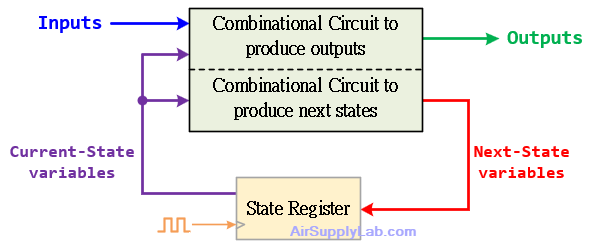
Figure 1: Synchronous Sequential Circuit
Basic Components:
- Flip-Flops: These are the building blocks of sequential circuits, storing a single bit of data. Flip-flops can be in one of two states, typically represented as 0 or 1, depending on their internal configuration and input signals.
- Registers: Registers are collections of flip-flops used to store multi-bit binary data. They are often employed to hold temporary data in digital systems.
- Counters: Counters are sequential circuits that produce a sequence of output values in response to clock pulses. They are commonly used in frequency division, timekeeping, and digital signal processing applications.
Design Procedure:
Designing sequential circuits typically involves the following steps:
- Specification:
- Begin by clearly defining the behavior and functionality of the circuit. Understand what the circuit needs to achieve.
- Specify the inputs, outputs, and any constraints or requirements.
- State Diagram:
- Create a state diagram that represents your circuit's states and state transitions.
- Each state is a circle, and arrows indicate transitions between states.
- State Minimization:
- Optimize the number of states to reduce complexity.
- Use techniques like state reduction, merging equivalent states, and removing unreachable states.
- Flip-Flop Selection:
- Choose appropriate flip-flop types based on the design requirements (e.g., D flip-flops, JK flip-flops).
- Prepare the excitation table for the selected flip-flops.
- State Table:
- Convert the state diagram into a state table.
- List all current states (their binary representations), inputs, next states, flip-flops inputs, and output values.
- Derive Equations:
- Use Karnaugh maps (K-Maps) to derive simplified flip-flop input and output circuit equations.
- Draw Logic Diagram:
- Draw the complete logic diagram incorporating combinational circuits for next-state output, flip-flops, and logic for output connections.
8.2 Finite State Machines
Finite State Machines (FSMs) are mathematical models used to represent the behavior of sequential circuits and systems. They describe the sequence of states a system can be in, the conditions under which transitions between states occur, and the actions taken in each state.
Representation:
- State Diagrams: Graphical representation showing states, transitions, inputs, and outputs.
- State Tables: Tabular representation of state transitions and outputs.
Types of FSMs:
- Moore Machines: Output depends only on the current state.
- Mealy Machines: Output depends on both the current state and inputs.
Moore S.M.
Moore State Machine
Moore Machines are a type of finite state machine (FSM) used to model sequential circuits where the output depends solely on the current state. Named after the computer scientist Edward F. Moore, these machines are widely employed in digital system design due to their simplicity and versatility.

Moore State Machine Block
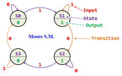 State Diagram for Moore State Machine
- Outputs depend on the current state only.
- Outputs change synchronously with state changes.
Mealy S.M.
Mealy State Machine
Mealy Machines are a type of finite state machine (FSM) used to model sequential circuits where the output depends on both the current state and the inputs. Named after the mathematician George H. Mealy, these machines offer versatility in capturing complex behaviors by associating outputs with transitions between states.

Mealy State Machine Block
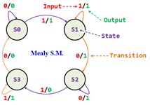
State Diagram for Mealy State machine
- Outputs depend on the current state and current inputs.
- Input change causes an immediate output change
- Asynchronous outputs
Moore S.M. v.s. Mealy S.M.
| Moore S.M. | Mealy S.M. | |
|---|---|---|
| Output Dependency |
|
|
| Timing of Output |
|
|
| Complexity and Efficiency |
|
|
| Applications |
|
|
8.3 State Diagram and State Table
State Diagram
State diagrams, also known as state transition diagrams or state charts, are graphical representations used to depict the behavior of finite state machines (FSMs) in digital logic design. They illustrate the various states that a system can be in, as well as the transitions between these states based on input signals.
Components of a State Diagram:
- States: Represent the different conditions or modes that the system can occupy. Each state is typically depicted as a circle or oval.
- Transitions: Arrows between states indicate the possible transitions based on input signals. These transitions specify the state change triggered by specific input conditions.
- Inputs: Input signals or conditions that cause state transitions. Inputs are usually labeled along the transition arrows.
- Outputs (Optional): Depicts the output generated by the system in each state. In Moore machines, outputs are associated with states, while in Mealy machines, outputs are associated with transitions.
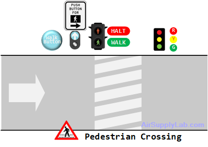
Example: Consider a simple pedestrian crossing controller
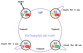
The diagram illustrates a single-lane road featuring a pedestrian crossing, where both vehicular traffic and pedestrians are regulated by light signals. Pedestrians have the option to request to cross the road by activating a designated walk button labeled as W.
Drawing State Diagrams:
The pedestrian crossing controller manages traffic flow on a single-lane road intersecting with a pedestrian crossing, utilizing light signals to regulate both vehicular and pedestrian movement.
- Pedestrian Request: Pedestrians can initiate a crossing request by pressing a designated walk button labeled W.
- Signal Sequence:
- Upon activation of the walk button W, the traffic light transitions from Green to Yellow for a duration of 5 seconds.
- Crossing Time:
- After the Yellow signal phase, the traffic light switches to Red, accompanied by the illumination of the pedestrian signal denoted as WALK. During this phase, a 20-second countdown initiates, allowing pedestrians to cross the road safely.
- Transition to Halt:
- Upon completion of the countdown, the WALK signal extinguishes, and a halt signal, denoted as HALT, activates for a brief duration of 1 second.
- Traffic Light Change:
- Subsequently, the Red light deactivates, and the green light switches on to facilitate vehicular movement.
Pedestrian Crossing Controller State Diagram:
The pedestrian crossing controller manages a single-lane road with a pedestrian crossing, regulating both road traffic and pedestrian movement through light signals. The controller responds to pedestrian requests initiated by pressing a walk button W, coordinating traffic light changes and pedestrian signals accordingly.
States:
- Pedestrian Requested (S0): The initial state where the system awaits a pedestrian request. Transitioned to upon detecting a pedestrian request ( W pressed).
- Yellow Light (S1): The traffic light transitions to yellow, signaling an impending change to red.
- Red Light (S2): The traffic light turns red, and the walk signal is activated.
- Countdown (S3): A countdown timer initiates after the walk signal is activated, signaling the time remaining for pedestrians to cross.
- Halt (S4): After the countdown, the walk signal turns off briefly, and a halt signal is activated.
- Green Light (S5): The traffic light transitions to green, allowing vehicular traffic to proceed.
Transitions:
- Pedestrian Requested (S0) ⟶ Yellow Light (S1): Triggered by a pedestrian pressing the walk button W.
- Yellow Light (S1) ⟶ Red Light (S2): The traffic light changes to red after a 5-second delay.
- Red Light (S2)⟶ Countdown (S3): Activates the countdown timer and walk signal.
- Countdown (S3) ⟶ Halt (S4): After the countdown, transitions to the halt phase.
- Halt (S4) ⟶ Green Light (S5): Transitions to the green light phase after a brief halt.
Inputs and Outputs:
- Inputs: Walk Button W, Timer Elapsed.
- Outputs: Traffic Lights (Green, Yellow, Red), Walk Signal, Halt Signal
Design the State Diagram:
- After reset, start from the S0 state.
- Draw arrows representing transitions between states, labeling them with applicable input conditions.
- Include outputs associated with each state or transition.
The following draft state diagram shows a single-lane road with a pedestrian crossing.
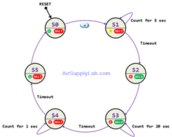
The Draft State Diagram for Pedestrian Crossing Controller
State Reduction:
After reviewing the draft state diagram, it is evident that certain states can be merged for optimization. For instance, combining S2 and S3 into a single state would streamline the diagram. Similarly, merging S5 and S0 would enhance clarity and efficiency in representing the system's behavior.
State Table
Creating a state table for a state machine in digital logic design is a fundamental step in the process of designing sequential circuits. Here are detailed instructions on how to create a state table:
- Define the States:
- Identify all possible states that the system can be in. States represent different conditions or modes of operation of the system.
- Assign a unique identifier (binary code or name) to each state.
- Determine Inputs:
- Identify the input signals that influence state transitions.
- List all possible input combinations.
- Determine Outputs:
- Determine the outputs for each state-input and input combination.
Construct the State Table:
- Create a table with columns representing states, inputs, and outputs (if applicable) and rows representing state transitions.
- Fill in the table with transition information:
- Current State: List all possible states in the leftmost column.
- Input: List all possible input combinations as column headers.
- Next State: Determine the state the system transitions to for each combination of current state and input.
- Flip-Flop Inputs: For flip-flops other than the D Flip-Flop, derive the inputs for each state bit from the current-state and next-state values using the excitation table of the chosen flip-flop.
- Output: If applicable, specify the output generated for each state-input combination.
Use the State Table for Design:
- Once the state table is complete, it serves as a blueprint for implementing the state machine using flip-flops, combinational logic, and other components.
- Translate the state table into logic equations or a state diagram for further design and implementation.
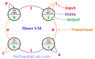
Example 01: Converting a Moore State Diagram to a State Table
Convert the provided Moore state diagram below into a state table using D flip-flops.
| Current State | Input | Next State | Output | ||
|---|---|---|---|---|---|
| A | B | X | An | Bn | F |
| 0 | 0 | 0 | |||
| 0 | 0 | 1 | |||
| 0 | 1 | 0 | |||
| 0 | 1 | 1 | |||
| 1 | 0 | 0 | |||
| 1 | 0 | 1 | |||
| 1 | 1 | 0 | |||
| 1 | 1 | 1 | |||
Using K-Map to find the An, Bn, and F:
| An | B X | ||||
| 00 | 01 | 11 | 10 | ||
| A | 0 | 0 | 1 | 3 | 2 |
| 1 | 4 | 5 | 7 | 6 |
An =
| Bn | B X | ||||
| 00 | 01 | 11 | 10 | ||
| A | 0 | 0 | 1 | 3 | 2 |
| 1 | 4 | 5 | 7 | 6 |
Bn =
| F | B X | ||||
| 00 | 01 | 11 | 10 | ||
| A | 0 | 0 | 1 | 3 | 2 |
| 1 | 4 | 5 | 7 | 6 |
F =
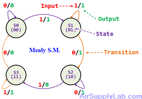
Example 02: Converting a Mealy State Diagram to a State Table.
Convert the provided Mealy state diagram below into a state table using D flip-flops.
| Current State | Input | Next State | Output | ||
|---|---|---|---|---|---|
| A | B | X | An | Bn | F |
| 0 | 0 | 0 | |||
| 0 | 0 | 1 | |||
| 0 | 1 | 0 | |||
| 0 | 1 | 1 | |||
| 1 | 0 | 0 | |||
| 1 | 0 | 1 | |||
| 1 | 1 | 0 | |||
| 1 | 1 | 1 | |||
Using K-Map to find the An, Bn, and F:
| An | B X | ||||
| 00 | 01 | 11 | 10 | ||
| A | 0 | 0 | 1 | 3 | 2 |
| 1 | 4 | 5 | 7 | 6 |
An =
| Bn | B X | ||||
| 00 | 01 | 11 | 10 | ||
| A | 0 | 0 | 1 | 3 | 2 |
| 1 | 4 | 5 | 7 | 6 |
Bn =
| F | B X | ||||
| 00 | 01 | 11 | 10 | ||
| A | 0 | 0 | 1 | 3 | 2 |
| 1 | 4 | 5 | 7 | 6 |
F =
Questions:
Q1:
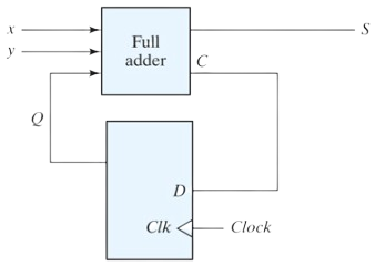
A sequential circuit has one flip-flop Q , two inputs x and y , and one output S . It consists of a full-adder circuit connected to a D flip-flop, as shown in the following diagram . Derive the state table and state diagram of the sequential circuit.
Q2:
A sequential circuit has two JK flip-flops A and B and one input x . The circuit is described by the following flip-flop input equations:
- ${J_A} = x$
- ${K_A} = B$
- ${J_B} = x$
- ${K_B} = \overline A $
- Derive the state equations An and Bn by substituting the input equations for the J and K variables.
- Draw the state diagram of the circuit.
Q3:
A sequential circuit has two JK flip-flops A and B , two inputs x and y, and one output z . The flip-flop input equations and circuit output equations are
- ${J_A} = B\,x + \overline B \,\overline y $
- ${K_A} = \overline B \,x\,\overline y $
- ${J_B} = \overline A \,x$
- ${K_B} = A + x\,\overline y $
- $z = A\,\overline x \,\overline y + B\,\overline x \,\overline y $
- Draw the logic diagram of the circuit.
- Tabulate the state table.
- Derive the state equations for A and B.
Q4:
For the circuit described by the state diagram of the following figure:
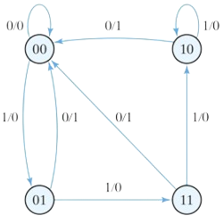
- Determine the state transitions and output sequence that will be generated when an input sequence of 010110111011110 is applied to the circuit and it is initially in the state 00.
- Find all the equivalent states in Figure and draw a simpler but equivalent state diagram.
- Using D flip-flops, design the equivalent machine (including its logic diagram) described by the state diagram in (b).
Q5:
Design a sequential circuit with two D flip-flops A and B , and one input x.
- When x = 0, the state of the circuit remains the same.
When x = 1, the circuit goes through the state transitions from 00 to 01, to 11, to 10, back to 00, and repeats. - When x = 0, the state of the circuit remains the same.
When x = 1, the circuit goes through the state transitions from 00 to 11, to 01, to 10, back to 00, and repeats.
Q6:
Design a sequential circuit with two JK flip-flops A and B and two inputs E and F . If E=0, the circuit remains in the same state regardless of the value of F .
- When E=1 and F=1, the circuit goes through the state transitions from 00 to 01, to 10, to 11, back to 00, and repeats.
- When E=1 and F=0, the circuit goes through the state transitions from 00 to 11, to 10, to 01, back to 00, and repeats.
Q7:
A sequential circuit has three flip-flops A, B, and C ; one input x ; and one output y . The state diagram is shown in the following Figure.
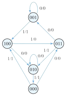
The circuit will be designed by treating the unused states as don’t-care conditions. Analyze the circuit obtained from the design to determine the effect of the unused states.
- Use D flip-flops in the design.
- Use JK flip-flops in the design.
- Use T flip-flop in the design.
