PSpice 01: DC Circuit Analysis
In this session, you will learn how to create a PSpice project to simulate the electronic circuit.
Procedures
1. Create a PSpice Project
Start up OrCAD Capture CIS
- To use PSpice, start with OrCAD Capture CIS program.
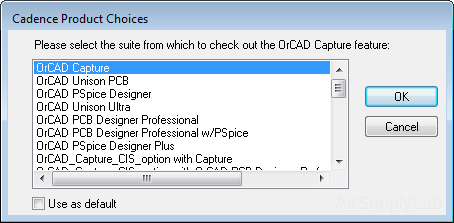
- The following windows may appear, then select "OrCAD Capture" and click OK.
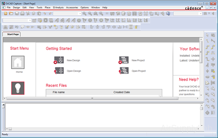
- When you start up you will get a screen which looks like this:
Create a new Project for PSpice
Next, you will use Capture to create a PSpice project and simulate the circuit on your computer.
Before you create a new project, it is recommended that you create a directory to store all your projects and files. For example, you can have a directory "PSpice" on the windows desktop ready beforehand.
Let's create your first PSpice project now.
- In the main Capture menu, select "File ➤ New ➤ Project...". The following window will appear. Be sure that the Analog or Mixed A/D button is selected (see figure below) Change it if necessary. This is VERY important.
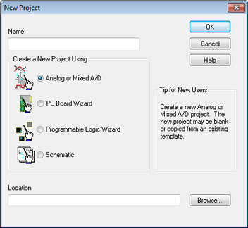
You will need to fill in the top line Name with a filename (use MyFirstPSpice) and then the bottom line Location with the pathname. This is the directory where you will be storing your "project". Click OK to continue the setup. - Now, the "Create PSpice Project" dialog will appear. Since you are starting a new project, you can change the setting to "Create a blank project" and then click OK.
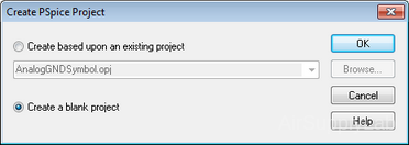
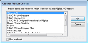
The default setting is "Create based upon an existing project: AnalogGNDSymbol.opi". You can use the default setting.- For the older version, the Cadence Product Choices window may appear. You have to select "PSpice A/D", and then click OK.
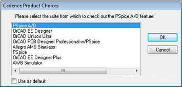
- For the older version, the Cadence Product Choices window may appear. You have to select "PSpice A/D", and then click OK.
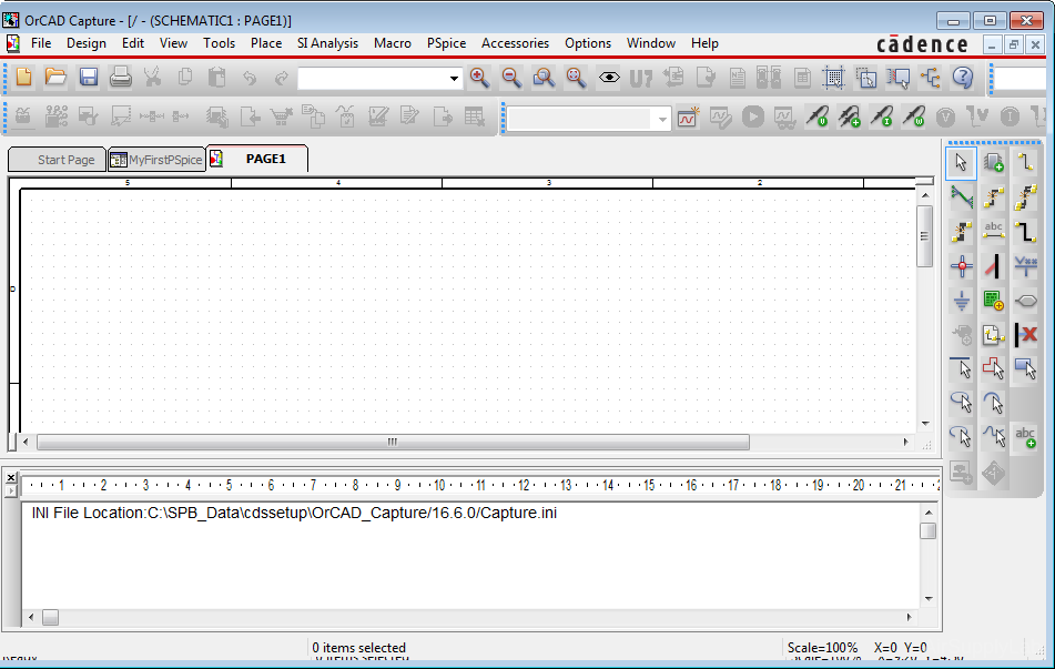
- Now, you should come up with a blank schematic entry screen.
2. Draw the Electronic Circuit
Add Components
You can now start adding components and symbols to the schematic. There are two ways to put in a component:
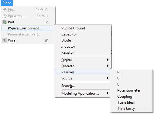
- In the main menu, select "Place ➤ PSpice Component..."
- Or you can click
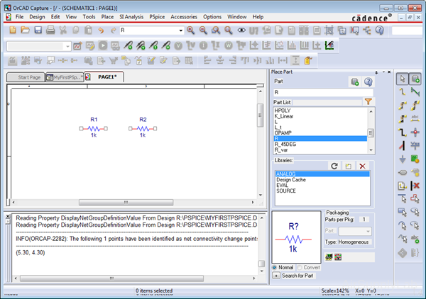
 Place Part button on the right-hand side toolbar to open the Place Part dialog box which will allow you to select parts from libraries. If the part you want is not on the list, try another library. Or you can add other libraries into the list by clicking
  Add Library button. There you will find a list of available libraries. For example, transistors and switches will be in eval.olb library; Resistors/Capacitor/Inductors are in analog.olb library; power sources are in source.olb libraries.
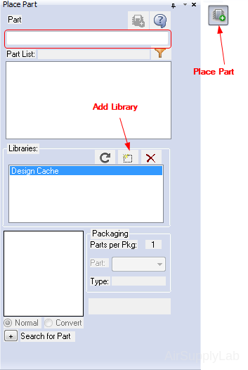
Note: Only the parts from the Libraries list box that are highlighted are shown in the Part List select box.
- Select the part you want and place it on the schematic:
Rotate the Component
You may need to rotate the component on the schematic.
- You can rotate parts by clicking on it to highlight it, then right-click the mouse to bring up the part menu. Select "Rotate" function to rotate the component.
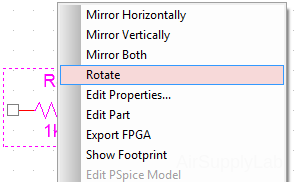
- Or, click the component to highlight it, then press "R" key to rotate the component.
Placement of All the Parts and GND
Continue placing the components you need.
- You can change the value of a component by double-click on the component value, and entering a new value.
- Connect the components together by placing wires (click Place ➤ Wire from the main menu, or click
 button).
 - Be sure to place PSpice Ground
 (click Place ➤ PSpice Component ➤ PSpice Ground from main menu).
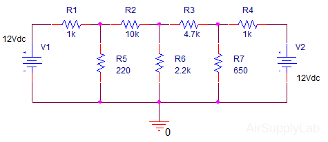
 - When you are done you will have something which looks like this:
- Then, save your schematic.
3. Create PSpice Simulation Profile
Be sure to save the file, then you can start the simulation process.
- Click PSpice ➤ New Simulation Profile from the main menu, or click
 button on the toolbar.
The following dialog will appear: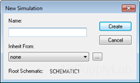
Give the New Simulation a Name. From now use "DC_Analysis". Then click the Create button. - The system may pop up a "Cadence Product Choices" windows, select the PSpice A/D and then click OK.
- The Simulation Setting window will appear:
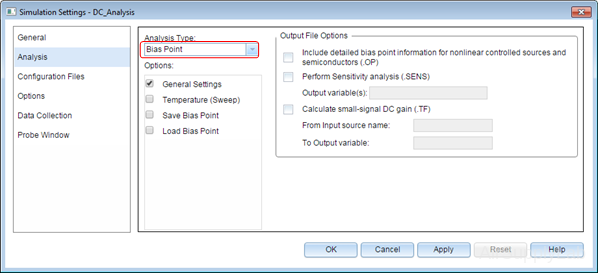
For a DC analysis, select Bias Point setting in the Analsys Type list. Click OK to close the window and go back to the main screen. - Now you are ready to Run a simulation. Click PSpice ➤ Run from the main menu, or click
 button on the toolbar. A simulation window will appear and will be closed when the simulation has completed.
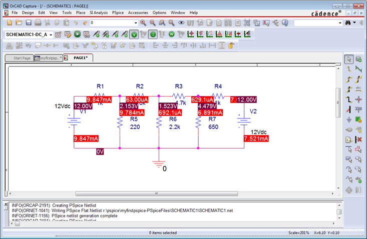
- When the
 ,
,  and
and  buttons are activated, the results of the voltage, the current and the power dissipated in that component will be shown on the schematic. The tool buttons
  ,
,  and
and  allow you to alternately toggle a highlighted value ON and OFF.
4. Dependent Sources


Figure 4-1: Symbols for (a) Dependent Current Source and (b) Dependent Voltage Source
Dependent sources can be either voltage or current sources; Figure 4-1 shows the symbol for a dependent voltage source and a dependent current source. Since each type of source can be controlled by either a voltage or current, there are four types of dependent current sources:
 VCVS (Voltage Controlled Voltage Source) = E
 VCCS (Voltage Controlled Current Source) = G
 CCCS (Current Controlled Current Source) = F
 CCVS (Current Controlled Voltage Source) = H
Figure 4-2 illustrates the voltage-controlled dependent sources, and Figure 4-3 illustrates the current-controlled dependent sources. In all cases, some electrical circuit exists which has some voltage and current combination at its terminals. Either the voltage or current at these terminals is used to set the voltage or current of the dependent source. The parameters µ and β in Figures 4-2 and 4-3 are dimensionless constants. µ is the voltage gain of a VCVS and β is the current gain of a CCCS. The parameter r is the voltage-to-current ratio of a CCVS and has units of volts/ampere, or ohms. The parameter g is the current-to-voltage ratio of a VCCS and has units of amperes/volt, or siemens.

(a) Voltage-Controlled Voltage Source (VCVS)

(b) Voltage Controlled Current Source (VCCS)
Figure 4-2: Voltage-Controlled Dependent Sources
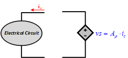
(c) Current-Controlled Voltage Source (CCVS)
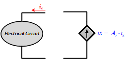
(d) Current-Controlled Current Source (CCCS)
Figure 4-3: Current-Controlled Dependent Sources
https://reference.digilentinc.com/learn/courses/real-analog-chapter-1/start
5. DC Sweep Analysis
PSpice has a feature that allows you to automatically change a part value within a specified range and to simulate and graph the results. This is called DC Sweep. DC Sweep allows you to sweep a source (voltage or current), a global parameter, a model parameter, or the temperature through a range of values. The bias point of the circuit is calculated for each value of the sweep. This is useful for finding the transfer function of an amplifier, the high and low thresholds of a logic gate, and so on.