Lab 01: Digital Multimeter Resistance Measurement
Objectives:
- To understand the concept of electric resistance and learn how to read color-coded ceramic resistors.
- To become familiar with the use of digital multimeter (DMM) in reading resistance, current, and voltage.
- To learn how to measure voltage and current with a digital multimeter.
Equipment:
Background:
Standard Resistor Values and Color
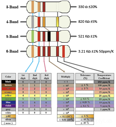
Resistors are color-coded for easy reading. To determine or calculator the resistance and tolerance value of a given resistor color, look for the gold or silver tolerance band and hold the resistor with this band to the right. Then read the resistor color code bands from left to the right, as shown in Figure 1.
Calculating Resistor Value
The Resistor Color Code system is all well and good but we need to understand how to apply it in order to get the correct value of the resistor. The left-hand or the most significant colored band is the band that is nearest to a connecting lead with the color-coded bands being read from left-to-right as follows:
Digit, Digit, Multiplier = Color, Color x 10 color in Ohm's (Ω)
For example, a resistor has the following colored markings;
Yellow-Violet-Red = 4 7 2 = 4 7 x 102 = 4700 Ω or 4.7 KΩ
The fourth and fifth bands are used to determine the percentage tolerance of the resistor. Resistor tolerance is a measure of the resistor's variation from the specified resistive value and is a consequence of the manufacturing process and is expressed as a percentage of its "nominal" or preferred value.
Typical resistor tolerances for film resistors range from 1% to 10%, while carbon resistors have tolerances up to 20%. Resistors with tolerances lower than 2% are called precision resistors with lower tolerance resistors being more expensive.
Most five band resistors are precision resistors with tolerances of either 1% or 2% while most of the four band resistors have tolerances of 5%, 10%, and 20%. The color code used to denote the tolerance rating of a resistor is given as:
Brown = 1%, Red = 2%, Gold = 5%, Silver = 10 %
If the resistor has no fourth tolerance band then the default tolerance would be at 20%.
Example #1: Resistor Color Coded

A resistor colored: Yellow-Violet-Orange-Gold would be 47×103 = 47 KΩ with tolerance ± 5%.

A resistor colored: Green-Red-Gold-Silver would be 52×10-1 = 5.2 Ω with tolerance ± 10%.

A resistor colored: White-Violet-Black would be 97×100 = 97 Ω with tolerance ± 20%. There are only three color bands on a resistor, which is a 4-band code with a blank/none (20%) tolerance band.

A resistor colored: Orange-Orange-Black-Brown-Violet would be 330×101 = 3.3 KΩ with tolerance ± 0.1%.
Example #2: Resistor Color Coded

A resistor colored: Brown-Green-grey-Silver-Red would be 158×10-2 = 1.58 Ω with tolerance ± 2%.

A resistor colored: Blue-Brown-Green-Silver-Blue would be 615×10-2 = 6.15 Ω with tolerance ± 0.25%.
Procedure:
Exp #1: Nominal and Experimental Values
Obtain about 15 resistors of the same nominal value. Measure the resistance of each resistor using the DMM range that will give the maximum number of significant figures. Make a table for all 15 resistors same as Table 1, and draw a distribution graphic with the vertical axis being the number of resistors with a 1% range. The horizontal axis is the percentage deviation from the nominal resistance value.
Data Table 1-1: Resistances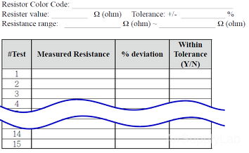
Data Table 1-2: The Percent Deviation
Figure 1: Distribution Graph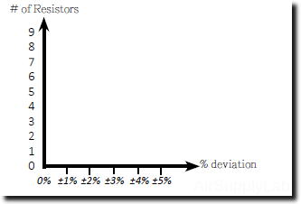
$\% deviation = \% d = \frac{{\left| {ExpValue - NominalValue} \right|}}{{NominalValue}} \times 100\%$
Exp #2: Percent Difference
Obtain a Resistance Substitution Box and use a DMM to measure the resistance values for all of the resistance setting to the maximum number of significant figures. Compare the actual resistance values to the nominal values in terms of the percent difference.
Data Table 2: The Percentage Difference
$\% Difference = \% diff = \frac{{\left| {Valu{e_1} - Valu{e_2}} \right|}}{{\left( {\frac{{Valu{e_1} + Valu{e_2}}}{2}} \right)}} \times 100\%$
Exp #3: Resistance in a Wire
Connect short lead or jumper wire using your red and black wire between the DMM input terminals and read the resistance, using the lowest resistance range to obtain the maximum number of significant figures. Now connect the long lead wire to the DMM and repeat the measurement. Calculate the approximate values of resistance per foot of the lead wire. Use the DMM NULL for easier measurement of this.

| Cable 1 Length (L1): inch | Resistance (R1): Ω |
| Cable 2 Length (L2): inch | Resistance (R2): Ω |
$Resistance\;per\;foot = Wir{e_{Resistance,foot}} = \frac{{{R_2} - {R_1}}}{{\left( {\frac{{{L_2} - {L_1}}}{{12}}} \right)}}\;\Omega$
Exp #4: Potentiometer
Variable Resistors: Obtain a 5000 Ω variable resistor (potentiometer or rheostat).
- Measure the total (i.e., end-to-end) resistance.
- Measure the resistance between the "wiper arm" and one end with the knob in the fully clockwise position and then with the knob in the fully counter-clockwise position. Then repeat this for the resistance between the wiper arm and the other end of the resistor.
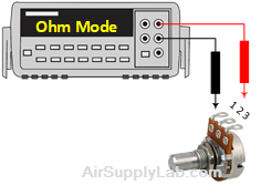
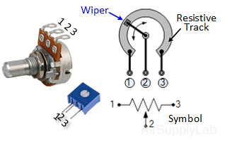
Data Table 4: The Resistances for Potentiometer
Exp #5: Voltage Produced by Ohmmeter
In some cases, especially when using the DMM to measure resistance values associated with various electronic devices, it is important to know the voltage produced by the DMM when measuring resistance. Connect the DMM to a resistance substitution box, and for every DMM resistance range, adjust the resistance to give a reading as close to the full-scale resistance reading as possible. Connect a second DMM set to read voltage across (in parallel with) the first DMM and read the test voltage of the first DMM.

Data Table 5: Voltage Produced by Ohmmeter in Difference Resistances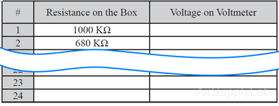
Questions:
- Give the 4-band color codes for the following resisters:
- 2Ω ±5%
- 0.5Ω ±10%
- 1KΩ ±20%
- The highest resistance range on a DMM is 20 MΩ. To measure a huge unknown resistor Rx, the unknown resistor is placed in parallel with a resistor that has previously been measured and has an actual value of 19.95 MΩ. The resulting DMM reading is 18.16 MΩ. Find the value of Rx.
