Rotary Encoder
Rotary encoders are sensors used in embedded systems to measure a rotating shaft's rotation, position, or angular movement. They convert a shaft's angular position or motion into digital or analog output signals, which microcontrollers or embedded systems can process. Rotary encoders are widely used in applications where precise control of position, direction, or speed is essential, such as robotics, motor control, industrial automation, and consumer electronics.
There are two main types of rotary encoders: incremental and absolute.
- Incremental Encoders: These generate pulses as the shaft rotates, allowing the system to detect the relative position and speed. However, they don't track the exact position and need a reference point for full positional awareness.
- Absolute Encoders: These encoders provide a unique position value for each rotation angle, enabling accurate position tracking without needing a reference point.
Most rotary encoders consist of an optical or magnetic disc attached to a shaft and a sensor that detects changes in the disc pattern as the shaft rotates. The output from a rotary encoder is often a series of pulses, which embedded systems use to determine speed, direction, and position by counting and interpreting these signals.
Incremental Encoders
Incremental Encoders


An incremental encoder is a rotary encoder that generates a series of pulses as the shaft rotates. It does not give an absolute position but provides information about the movement direction and speed by counting pulses. Incremental encoders are widely used in applications like motor control, where relative positioning or speed is essential.
Key Components of an Incremental Encoder
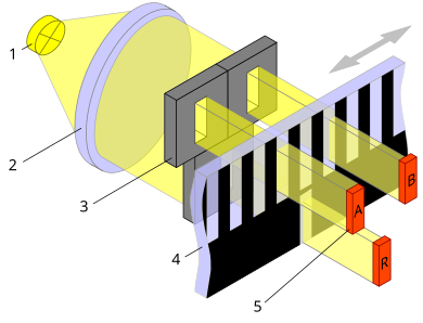
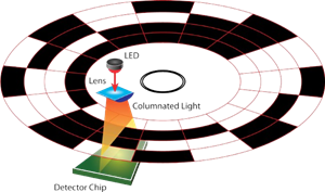
- Disk: A rotating disk with alternating transparent and opaque sectors.
- LED or Light Source: Illuminates the disk.
- Photodetector: Detects light patterns through the disk and generates pulses.
- Metal Ring with Contact Points: In some designs, a metal ring with tabs or protrusions makes contact with internal conductive segments to produce pulses mechanically.
Working Principle
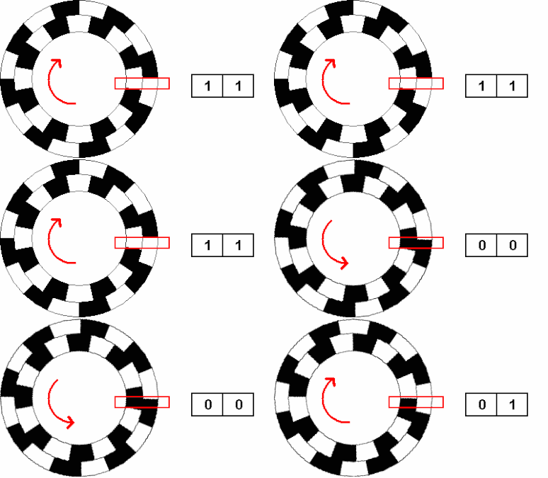
As the shaft rotates, the photodetector senses light through the disk's alternating sectors, or in mechanical designs, the metal ring’s tabs make and break contact with the internal contact points. This pattern is converted into a square wave, creating pulses representing shaft movement.
- Channels (A and B): Incremental encoders often have two output channels, A and B. These channels produce square waves with a 90° phase difference (quadrature output). This phase shift allows the determination of both speed and direction of rotation.
- Index Pulse (Z): Some encoders include an index pulse (Z channel) that generates a single pulse per revolution, serving as a reference position.
Determining Direction
By reading both Channel A and Channel B, the direction of rotation can be determined:
- Clockwise (CW): Channel A leads Channel B.
- Counter-Clockwise (CCW): Channel B leads Channel A.
How to Detect the Rotation Speed of an Incremental Encoder
Detecting the rotation speed of an incremental encoder involves measuring the frequency or time between pulses generated by the encoder’s output channels (Channel A and/or Channel B). Here are common methods used to calculate rotation speed:
- Pulse Counting with a Fixed Time Interval
- In this method, the system counts the number of pulses the encoder generates within a fixed time interval.
- For example, suppose the encoder produces 100 pulses in one second, and each pulse represents a fixed angular movement. In that case, the speed can be calculated by multiplying the number of pulses by the angular movement per pulse.
- This method works well for steady speeds but may not capture rapid speed changes accurately.
Formula: $Speed\, (in\, degrees/\sec ) = {{Number\, of\, Pulses \times Degree\, per\, Pulse} \over {Time\, Interval}}$ - Time Measurement between Pulses
- Another approach is to measure the time interval (in microseconds or milliseconds) between consecutive pulses on a single channel (e.g., Channel A).
- This interval can be inversely proportional to the speed. The shorter the interval between pulses, the higher the speed.
- This method is especially useful for detecting changes in speed in real time.
Formula: $Speed\, (in\, RPM) = {{60 \times Pulse\, per\, Revolution} \over {Time\, between\, Pulse}}$ - Using Quadrature Signals for Higher Precision
- Since incremental encoders generate two channels (A and B) with a 90° phase difference, they can provide higher resolution when both channels are read. Each transition (rising and falling edges) can be treated as an individual pulse.
- By counting all transitions in both channels, you effectively quadruple the pulse count per revolution, which allows for more precise speed calculations.
Absolute Encoders
Absolute Encoders


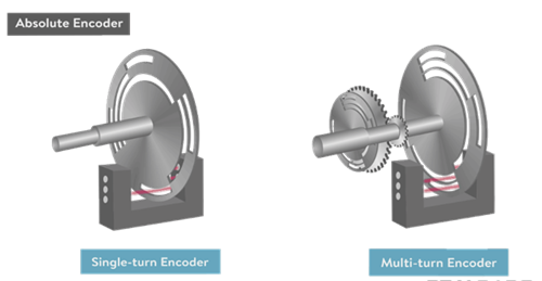
An absolute encoder provides a unique code or output for each position, allowing it to track the exact angular position of the shaft at any given moment. Unlike incremental encoders, absolute encoders retain the position information even when powered off, making them ideal for applications that require precise positioning, such as robotics, CNC machines, and industrial automation.
Types of Absolute Encoders
- Single-Turn Absolute Encoder:
- Provides unique position information within a single 360° rotation.
- Each position within one rotation has a unique digital code.
- Resets to the initial position after one complete turn.
- It is ideal for applications requiring precise positioning within a single turn, such as servo motors and rotary controls.
- Does not track multiple turns or rotations.
- Multi-Turn Absolute Encoder:
- Records the angle within a single rotation and the number of complete rotations.
- Can uniquely identify positions across multiple revolutions.
- Retains position data even after several turns, allowing for precise multi-turn tracking.
- Suitable for applications requiring accurate positioning over multiple turns, such as in elevators, robotics, and industrial automation.
- Maintains position information even if power is lost, ensuring reliability for critical applications.
