Universal Asynchronous Receiver-Transmitter (UART)
A Universal Asynchronous Receiver/Transmitter, abbreviated UART (pronounced ' you-art '), is an asynchronous serial communication protocol. The universal designation indicates that the data format and transmission speeds are configurable. UART is a very useful interface that can transmit signals without needing to synchronize with a clock signal. This method of transmission is extremely useful for reducing wires and I/O pins compared to parallel systems which transmit data faster but are far more complex. It provides a cost-effective simple and reliable communication between one controller to another controller or between a controller and host computer.
In the UART system, the parallel data is reformatted into a serial stream and then sent out through the transmitting wire. In the simplest connection form, a UART can be thought of as a two-wire communication system where one line is transmitting and the other is receiving. UART can be configured for Full Duplex, Half Duplex, RX-only, or TX-only versions.
UARTs are commonly used in conjunction with a communication standard such as RS-232 or RS-485. The voltage levels of RS-232 are -12V and +12V. Usually, all the digital systems work on TTL or CMOS voltage levels, which are not directly compatible with those of RS-232, a level transition buffer such as MAX232 must be used.
Data Packet Format
UART-transmitted data is organized into packets. Each packet contains [1 START bit ] + [ DATA frame (5 ~ 9 bits) ] + [ PARITY bit (optional) ] + [ STOP bit (1, 2) ], as shown in the following diagram.
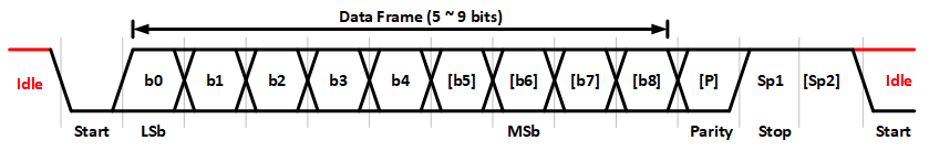
- START bit
In the Idle mode, the UART data line is held at a high voltage level (logic 1). To start data transmission, the transmitting UART pulls the transmission line to low for one clock cycle. When the receiving UART detects the data line from high to low voltage transition, it begins reading the bits in the data frame at the frequency of the baud rate. - DATA frame
The data frame contains the data being transferred. Options are 5, 6, 7, 8 (default), or 9. If the PARITY bit is not used, the length of the data frame could be up to 9 bits; if a parity bit is used, the maximum length of the data frame is up to 8 bits. - PARITY bit
The parity bit is for error checking when the receiving UART receives a packet. This can be set to None (default), Odd, Even, or Mark/Space. If the data frame is 9-bits, then the Parity type must be Mark/Space. The parity bit is optional and it is actually not that widely used. - STOP bits
To signal the end of the data packet, the sending UART drives the data transmission line from a low voltage to a high voltage. The STOP bit can be set to 1 (default) or 2 bits.
Baud Rate
The baud rate specifies how fast data is sent over a serial line. The units of the baud rate are bit-per-second (bps). The higher the baud rate goes, the faster data is sent and received, but the speed of data transfer is limited. Since there is no clock signal in the UART communication, the higher transmitting speed will easily lead to errors on the receiving end. Therefore, each of the two UARTs must be communicating using a known baud rate or bit frequency. The receiver and transmitter clock rates must be within 5% to avoid errors.
There are different sets of standard baud dates used depending on the application. Usually, the baud rates use 1200, 2400, 4800, 9600,19200, 38400, 57600 and 115200 bps. Both the local and remote UARTs must be configured for the same baud rate.
How does UART work?
UARTs transmit data asynchronously, which means there is no clock signal to synchronize the data bits from the transmitting UART to the receiving UART. Typically, asynchronous communication needs handshaking signals to ensure sender and receiver coordinate data transfers. In the UART, there are no extra handshaking signals between the transmitter and receiver. The transmitter generates a bitstream based on its clock signal, and then the receiver's goal is to use its internal clock signal to sample the incoming data. Therefore, the transmitter and receiver both need to have the same transfer speed and data packet format. Then, the receiver's UART resynchronizes the internal clocks on the falling edge of the start bit and then reads the center of each expected data bit based on the baud rate that is set.
UART Flow Control
UART Flow Control is a method for slow and fast devices to communicate with each other over UART without the risk of losing data.
Consider the case where two units are communicating over UART. A transmitter T is sending a long stream of bytes to a receiver R. R is a slower device than T, and at some point, R cannot keep up. It needs to either do some processing on the data or empty some buffers before it can keep receiving data.
R needs to tell T to stop transmitting for a while. This is where flow control comes in. Flow control provides extra signaling to inform the transmitter that it should stop (pause) or start (resume) the transmission.
Several forms of flow control exist. For example, hardware flow control uses extra wires, where the logic level on these wires defines whether the transmitter should keep sending data or stop. With software flow control, special characters are sent over the normal data lines to start or stop the transmission.
Hardware Flow Control: also called RTS/CTS Flow Control
When hardware flow control is enabled, two extra wires are needed in addition to the data lines. They are called RTS (Request to Send) and CTS (Clear to Send). The CTS signal is an input to the UART that is set by the other UART in the system when it is OK to send data on the bus. The RTS signal is an output of the UART informing the other UART on the bus that it is ready to receive data. The RTS line of one UART is connected to the CTS line of the other UART and vice versa. These lines are only valid before transmission is started. If the signal is set or cleared after a transfer is started the change will only affect the next transfer.
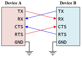
Figure 2: The Connection for Hardware Flow Control
Software Flow Control
Software flow control does not use extra wires. Only 3 wires are required (RX, TX, and GND). Transmission is started and stopped by sending special flow control characters. The flow control characters are sent over the normal TX and RX lines. The flow control characters are typically the ASCII codes XON and XOFF (0x11 and 0x13). If device A sends XOFF to device B it means that B should halt transmission to A until B receives an XON character from A.

Figure 3: The Connection for Software Flow Control
UART Configurations
Both UART communicating devices must operate at the same baud rate and have the same configuration for successful communication:
- Baud Rate
- Standard Mode: 110 to 115,200 bps
- Fast Mode: 230,400 ~ 921,600 bps, up to 4 Mbps
- Modes: Full-duplex, half-duplex, TX only, RX only
- Data Bits: 5 ~ 9 bits
- Endianess: Some UART devices offer the option to send the data in either LSb or MSb. The UART is almost always LSb.
- Parity Types: None, Even, Odd, Mark/Space
- Stop Bits: 1 or 2
- Flow Control: None, Hardware (CTS/RTS), Software (Xon/Xoff)
The most common configuration for UART is often listed as "8N1", which is shorthand for eight data bits, no parity, and one-stop bit. This is the default configuration for the UART communication protocol. Therefore, you only need to set the baud rate in most applications.