RC Servo
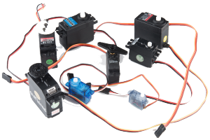
RC Servo is a type of gear motor that is designed with limited rotation angles like 60°, 90°, 180°, and so on. It is great for beginners who want to make stuff move without building a motor controller with feedback and a gearbox. Originally used in remote-controlled cars and airplanes. It is controlled by sending a PWM signal from the microcontroller. The PWM signal tells the servo what position it should move to.
- The servo can be positioned from 0 to 180 degree
- An internal DC motor connected to a potentiometer
- High torque gearing
- Internal feedback circuitry to control motor position
Connector and Wire Colors
Most standard RC servos use a standard type of 3-pin plug. The connector is a female, 3-pin, 0.1" (2.54 mm) pitch header. The wiring color used on the servo is not always consistent, there are several color codes at play. But the pins are usually in the same order, just the colors are different.
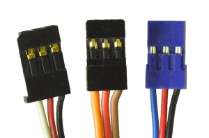
- Red wire — Servo power (Vservo, battery positive terminal)
- Brown or Black wire — Ground (GND, battery negative terminal)
- Orange, Yellow, white, or blue wire — Servo control signal line (PWM signal)
Please check the datasheet or specs for your servo to determine the proper power supply voltage, and please take care to plug the servo into your device in the proper orientation. Plugging it in backward could break the servo.
Control Signal
The third pin of the servo connector carries the control signal, used to tell the motor where to go. This control signal is a PWM signal. The frequency of PWM is in a range of 40 Hz to 200 Hz. Typically, the servo uses a 50 Hz (20 ms period) PWM signal. The servo position is not defined by the PWM duty cycle, but only by the pulse width. Since the position of the servo is determined by the width of the "on" pulse. The off-time can be from 5 ms to 40 ms, without any impact on the position. Different servos may have different minimal and maximal pulse widths. Usually, the pulse width is in the range of 1 ms to 2 ms. The servo will rotate in the clockwise or counter-clockwise direction. The direction of rotation of the digital servos can be changed by a specific programmer device. The neutral is defined to be the center of rotation. It is important to note that different servos will have different constraints on their rotation, but they all have a neutral position and that position is always a pulse width of 1.5 ms.
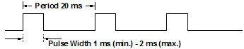 Figure 1: Typical PWM Signal for the Most of RC Servos
When the power is turned off, the servo's rotor stays in its position. This means that, when power is turned on again, the controller may not know the rotor's angle. For this reason, it's common to return the servo to the neutral position as soon as power becomes available.
Due to the fact that the servo is appropriate for hobbyists, a detailed datasheet may not available. However, the limiting values for signal width can be determined by the experiment.
Deadband width: Minimum pulse width (in microseconds) that the servo will respond to. determines the minimum move that can specify, 10 μs would be around 1.8º; 1 μs would be 0.18º.