Lab 03: Voltage Regulation and AC Power Supply
Objective
- Measure and understand voltage regulation by comparing no-load and full-load voltage conditions in a DC power supply.
- Calculate load regulation to assess how well a power supply maintains output voltage with varying load currents.
- Measure and analyze the AC ripple factor to evaluate the AC component present in the DC output under different load conditions.
- Explore and verify the AC output characteristics of a function generator by measuring AC voltage at different frequencies.
- Gain hands-on experience with digital multimeters (DMM) in measuring DC and AC voltages, ripple, and output stability.
Equipment
Background
Power Supply Regulation
An ideal DC power supply provides a constant DC voltage despite the change to the input voltage or load conditions. The output voltage of a real DC power supply changes under load, as shown in Figure 1(b). The output is also sensitive to input voltage changes.
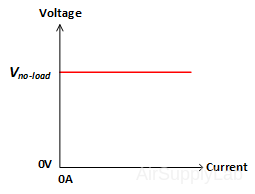
Figure 1: (a) Ideal Power Supply
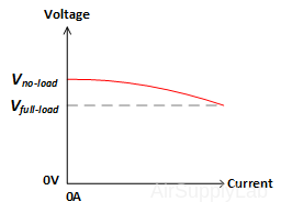
(b) Real Power Supply
Voltage Regulation, Line Regulation, and Load Regulation are key parameters for evaluating the stability and performance of DC power supplies. Here’s an overview of each:
Voltage Regulation
Voltage Regulation
- Refers to the overall ability of a power supply to maintain a constant output voltage despite changes in load current or input voltage. It essentially indicates the deviation of the output voltage from a set reference.
- Usually expressed as a percentage, showing how much the output voltage varies from a nominal value under specified conditions.
- The lower the percentage (closer to zero), the more stable the secondary voltage and the better the regulation it will provide.
- Formula:
\(\% VR = VoltageRegulation (\%) = {{{V_{no - load}} - {V_{full - load}}} \over {{V_{full - load}}}} \times 100\% \) - Where:
- Vno-load: Output voltage when no load is connected.
- Vfull-load: Output voltage when the full load is connected.
Line Regulation
Line Regulation
- It focuses on the power supply’s ability to maintain its output voltage as the input (or “line”) voltage changes.
- For example, if the input voltage fluctuates, line regulation tells us how much the output voltage will deviate due to this change.
- Typically measured in terms of percentage change in output voltage per unit change in input voltage (e.g., %/V) or as a simple percentage over a specified input voltage range.
- Formula:
\(\% LR = LineRegulation (\%) = {{{V_{\max }} - {V_{\min }}} \over {{V_{nominal}}}} \times 100\% \) - Alternatively, it can be expressed as a percentage change in output voltage per unit change in input voltage, typically as \({{\Delta {V_{out}}} \over {\Delta {V_{in}}}} \times 100\% \)
- Line regulation can also be expressed in terms of percent change in VOUT per volt change on the VIN (%/V):
\(\% /V = {{\Delta {V_{OUT}}} \over {\Delta {V_{IN}} \times {V_{OUT}}}} \times 100\% \) - Where:
- 𝑉max and 𝑉min: Maximum and minimum output voltages observed due to input voltage fluctuations.
- 𝑉nominal: Nominal (or target) output voltage.
Example:
A 12 V power supply at its designed load and at a constant temperature of 25ºC provided 12.000 V when the input voltage was 12.50 V, but provided 12.012 V when the input was 18.50 V. Fine the LR.
& Input \Rightarrow Output \cr
& 12.50V \Rightarrow 12.00V \cr
& 18.50V \Rightarrow 12.012V \cr} $
\(LR = {{(12.012 - 12)} \over {(18.50 - 12.50) \times (12)}} \times 100\% = 0.016 \,\% /V\)
Load Regulation
Load Regulation
- It deals with how well the power supply maintains its output voltage as the load on it changes, i.e., as the current drawn by the load varies.
- Load regulation is important in applications where the power demand fluctuates significantly.
- It is typically expressed as a percentage change in output voltage for a specified range of load currents (from minimum to maximum load).
- Formula:
\(LoadRegulation (\%) = {{{V_{no - load}} - {V_{full - load}}} \over {{V_{nominal}}}} \times 100\% \) - Load regulation can also be expressed in terms of the percent change in the output per mA change in load current (%/mA).
- Where:
- 𝑉no-load: Output voltage when no load is connected.
- 𝑉full-load: Output voltage at full load.
- 𝑉nominal: Nominal output voltage.
Example 1
Example 1:
Q: What would be the load regulation for a power supply that provides 12 V under minimum load and 11.5 V under maximum load?
Detailed Answer:
To calculate load regulation, we can use the formula: \(LoadRegulation (\%) = {{{V_{no - load}} - {V_{full - load}}} \over {{V_{nominal}}}} \times 100\% \)
In this case:
- 𝑉no-load = 12 V
- 𝑉full-load = 11.5 V
- Assuming 𝑉nominal = 𝑉full-load = 11.5 V (we typically use the full-load voltage as the nominal value in load regulation calculations).
Plugging in the values:
\(LoadRegulation (\%) = {{12 - 11.5} \over {11.5}} \times 100\% = 4.35\% \)
Calculating this:
- The difference between no-load and full-load voltages is 12 − 11.5 = 0.5 V
- Divide by the nominal voltage (full-load voltage): \({{0.5} \over {11.5}} \approx 0.0435\)
- Convert to a percentage: 0.0435 × 100% = 4.35%
Answer:
The load regulation for this power supply would be approximately 4.35%. This means the output voltage drops by 4.35% when the load increases from minimum to maximum.
Example 2
Example 2:
Q: What is the load regulation for a 12 V power supply that provides 12.000 V when only a voltmeter is used, and 11.940 V when the load is at its minimum, as specified in the datasheet, at a constant temperature of 25ºC?
Detailed Answer:
To calculate load regulation, we use the following formula: \(LoadRegulation (\%) = {{{V_{no - load}} - {V_{full - load}}} \over {{V_{nominal}}}} \times 100\% \)
In this case:
- 𝑉no-load = 12.000 V
- 𝑉full-load = 11.940 V
- Assuming 𝑉nominal = 𝑉full-load = 11.940 V
\(Load = {{12 - 11.94} \over {11.94}} \times 100\% = 0.5\% \)
The load regulation for this power supply would be approximately 0.503%. This indicates that the output voltage decreases by about 0.503% when a minimum load is applied, compared to the voltage with no load.
Ripple and Noise
Ripple and Noise
Ripple identifies undesired AC components in the DC output voltage and includes the portions of the AC input voltage waveform that remain after filtering. It also includes electrical noise developed within a power supply. Ripple is generally stated in mVRMS or mVPP for series-regulated and switching-type power supplies. But ripple is given in percent of nominal-rated DC voltage for ferroresonant and unregulated supplies. Ripple in the output of series-regulated supplies is typically 0.25 to 5 mVRMS and 1 to 15 mVPP. Switching supply ripple runs from 5 to 20 mVRMS and 20 to 150 mVPP. Ripple for ferroresonant supplies typically is 0.5 to 5%, and that for unregulated supplies is 5 to 10%.
Most power-supply applications require DC voltage containing a very low ripple. For applications providing power for high-gain or low-power-level amplifiers, for example, power supplies should be chosen on the basis of VPP specifications rather than VRMS.
Other Characteristics
Other Characteristics that Affect Power Supply Output Voltage
The temperature coefficient is the percent change of output voltage as a result of a 1°C change in ambient temperature.
Power-supply stability is the percent change of output voltage as a function of time. A stability figure is often stated for warm-up, based on a short time, typically 20 min, as well as for long-term, typically a 24-hr period.
Summary of Differences:
- Voltage Regulation assesses overall stability of the output voltage.
- Line Regulation examines output stability in response to changes in input voltage.
- Load Regulation examines output stability in response to changes in load current.
Procedure
Exp #1: Voltage Regulation
- Connect the DC Power Supply to the Digital Multimeter (DMM) and set the DC Power Supply to give an output voltage of 10 V as read on the DMM. Read and record the DC voltage to the maximum number of significant figures.
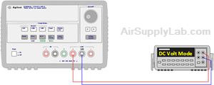
Figure 1: Measure the DC Voltage without Load - Connect a 50 Ω, 10-watt resistor across the DC Power Supply. Record the new value of the voltage. (Use the NULL for easier measurement.)
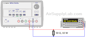
Figure 2: Measure the DC Voltage with Full-Load - Calculate the voltage regulation of the DC Power Supply as defined by:
\(VoltageRegulator = \frac{{{V_{no - load}} - {V_{full - load}}}}{{{V_{full - load}}}} \times 100\% \)
The Vno-load is the output voltage of the DC Power Supply when the output current is zero. The Vfull-load, in this case, is the output voltage when the output current is Vfull-load / 50 Ω.
- Calculate the output resistance RO of the DC Power Supply from the relationship
\({R_O} = \frac{{{V_{no - load}} - {V_{full - load}}}}{{{I_{full - load}} - {I_{no - load}}}}\)
Exp #2: AC Ripple Factor
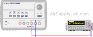
Figure 3: Measure the AC voltage without Load
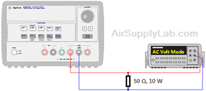
Figure 4: Measure the AC voltage with Full-Load
Set the DMM to read AC voltage. Read and record the AC voltage (in millivolts). Do this for both the full-load (50 Ω) and the no-load conditions. Calculate the DC Power Supply ripple factors for no-load and full-load as given by
\(Ripple\,Factor = \% R = \frac{{{V_{AC - Ripple}}}}{{{V_{DC}}}} \times 100\% \)
- %Rno-load = __________
- %Rfull-load = __________
Exp #3: AC Power Supply

Figure 5: Measure the AC voltage on the Function Generator
Connect a Digital Multimeter (DMM) to a FUNCTION GENERATOR. Set the DMM function control to read AC voltage. Adjust the frequency control of the FUNCTION GENERATOR to 1 KHz. Adjust the amplitude control to give an output voltage of 1VRMS as read on the DMM. Compare the volts peak-to-peak (VPP) reading on the FUNCTION GENERATOR to the DMM reading. Are they consistent?
- Increase the frequency up to the point where the DMM reading has changed by about 10%.
- Now reduce the frequency of the Function Generator to below 1 kHz, and decrease the frequency to the point where the DMM reading has changed by about 10%.
- DMM Input Impedance
Set the FUNCTION GENERATOR frequency to 100 Hz and adjust the output voltage to 1 VRMS. Connect a 1 MΩ resistor in series between the FUNCTION GENERATOR and the DMM. Now increase the frequency to 100 KHz. Read the DMM, and from the reading, calculate the DMM input capacitance.
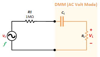
\[\eqalign{
& {V_S} = {{{V_{L1}}} \over {{R_L}}} \times ({R_1} + {X_{C1}}) + {V_{L1}} = {{{V_{L1}}} \over {{R_L}}} \times ({R_1} + {1 \over {2\pi {f_1}{C_L}}}) + {V_{L1}} \cr
& {V_S} = {{{V_{L2}}} \over {{R_L}}} \times ({R_1} + {X_{C2}}) + {V_{L2}} = {{{V_{L2}}} \over {{R_L}}} \times ({R_1} + {1 \over {2\pi {f_2}{C_L}}}) + {V_{L2}} \cr} \]
Questions
- What does a DC Power Supply do?
- Why is there an AC ripple present? And will a battery have an AC ripple?
- If a DC Power Supply has an output resistance of 10 mΩ (milli-ohms) and a no-load output voltage of 10 V, find the change in the output voltage and the load regulation for a full-load output current of 1 A.
- A DC Power Supply is adjusted to give a no-load output voltage of 10 V. The AC line voltage is 115 VRMS. When a full-load current of 1 A is drawn, the output voltage drops to 9.98 V. Find the no-load to full-load load regulation expressed in percent.
- When the AC line voltage drops from 115 V to 110 V, the DC output voltage decreases from 10 V to 9.95 V. Find the line regulation expressed in terms of %/V.
- If the DC output voltage is 10 V and the RMS AC ripple voltage on the output is 10 mV, find the percentage ripple factor.
- As the temperature varies from 25 °C to 35 °C, the output voltage increases from 10 V to 10.05 V. Find the temperature coefficient of the output voltage expressed (V/ºC).
Extra Questions
- There are two DC power supply devices. One has 10% voltage regulation, and another has 15%. Which one is better? Why?
- Given the circuit shown in Figure EQ2, do the following:
- Find the no-load value of VO.
- Determine VO when RL is 450 KΩ.
- Determine the load regulation if the no-load voltage represents the minimum load condition and the with-load setup represents the full load as well as nominal load conditions.
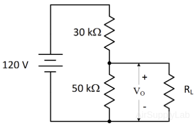
Figure EQ2: Circuit Diagram for Exter Question 2. - The nominal output voltage of a certain regulator is 8 V. The output changes by 2 mV when the input voltage goes from 12 V to 18 V. Determine the line regulation and repress it as a percentage change.