Lab 08: Kirchhoff's Voltage Law and Kirchhoff's Current Law
Objective
- Verify Kirchhoff's Voltage Law (KVL) and Kirchhoff's Current Law (KCL) using mesh and nodal analysis of the given circuit.
Equipments
Background
Kirchhoff’s Voltage Law
Kirchhoff’s Voltage Law states that the algebraic sum of all the voltages around any closed path (loop or mesh) is zero: \(\sum\nolimits_i {{v_i}} = 0\)
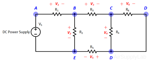
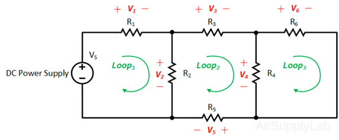
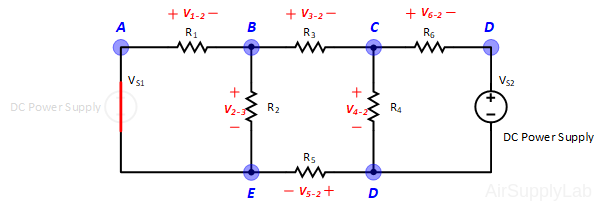
Applying Kirchhoff’s voltage law to the first and the second loops in the circuit shown in Figure 1 yields:
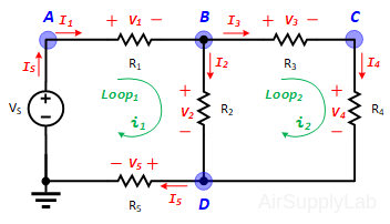
Figure 1: A simple circuit to illustrate KVL and KCL.
Loop Equations:
\(\begin{array}{l} Loo{p_1}:\quad - {V_S} + {V_1} + {V_2} + {V_5} = 0 & ....(1a)\\ Loo{p_2}:\quad - {V_2} + {V_3} + {V_4} = 0 & ....(1b) \end{array}\)
\(\begin{array}{l} Loo{p_1}:\quad - {V_s} + {i_1}({R_1} + {R_2} + {R_5}) - {i_2} \cdot {R_2} = 0 & ...(2a)\\ Loo{p_2}:\quad - {i_1} \cdot {R_2} + {i_2}({R_2} + {R_3} + {R_4}) = 0 & ...(2b) \end{array}\)
Kirchhoff’s Current Law
Kirchhoff’s Current Law states that the algebraic sum of all the currents at any node is zero: \(\sum\nolimits_i {{i_i}} = 0\)
Applying Kirchhoff’s current law to the first four nodes in the circuit shown in Figure 1 yields the following equations:
Node Equations:
\(\begin{array}{l} Nod{e_A}:\quad - {I_S} + {I_1} = 0\\ Nod{e_B}:\quad - {I_1} + {I_2} + {I_3} = 0\\ Nod{e_C}:\quad - {I_3} + {I_4} = 0\\ Nod{e_D}:\quad - {I_2} - {I_4} + {I_S} = 0 \end{array}\)
\(Nod{e_A}:\quad \frac{{{V_A}}}{{{R_1}}} - \frac{{{V_B}}}{{{R_1}}} - \frac{{{V_D}}}{{{R_5}}} = 0\)
\(Nod{e_B}:\quad - \frac{{{V_A}}}{{{R_1}}} + {V_B}(\frac{1}{{{R_1}}} + \frac{1}{{{R_3}}} + \frac{1}{{{R_5}}}) - \frac{{{V_C}}}{{{R_3}}} - \frac{{{V_D}}}{{{R_5}}} = 0\)
\(Nod{e_C}:\quad - \frac{{{V_B}}}{{{R_3}}} + {V_C}(\frac{1}{{{R_3}}} + \frac{1}{{{R_4}}}) - \frac{{{V_D}}}{{{R_4}}} = 0\)
\(Nod{e_D}:\quad - \frac{{{V_B}}}{{{R_2}}} - \frac{{{V_C}}}{{{R_4}}} + {V_D}(\frac{1}{{{R_2}}} + \frac{1}{{{R_4}}} + \frac{1}{{{R_5}}}) = 0\)
Procedure
Exp #1: KVL and KCL
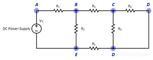 Figure 1: Exp #1 Circuit
- Obtain 6 randomly selected resistors with values between 1.0 KΩ and 10 KΩ. Measure the actual resistance values with a Digital Multimeter (DMM). The resistance range on the DMM should be chosen so as to obtain the maximum accuracy (i.e. maximum number of digits for the DMM reading). Compare the actual resistance values as determined by the DMM with the nominal resistance value as obtained from the color bands on the resistor. Determine If the actual resistance values are within the tolerance limits for each resistor.

- Construct the circuit shown in Figure 1. Adjust the supply voltages VS to +10 Volts.
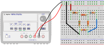
- Measure all branch voltages in circuit with a DMM. The measurements should be made with the DMM range chosen so as to obtain maximum accuracy (i.e. maximum number of digits) for each branch voltage measurement. Remember to keep proper track of the algebraic signs.
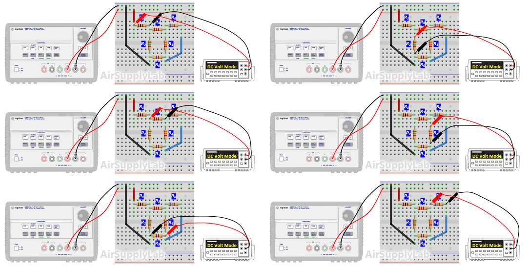
- Verify that Kirchhof's Voltage Law is satisfied for all of the loops in the circuit. From step 3 table (c), do they add (algebraically) to zero for each loop? Calculate the percentage error based on the following equation:
\(\% err = \frac{{\sum {{V_n}} }}{{\left[ {\frac{1}{n} \times \sum {\left| {{V_n}} \right|} } \right]}} \times 100\% \)
Data Table 2: Total Voltage in Each Loop

Does the percentage error obtained seem reasonable in view of the accuracy of the DMM? - From the branch, voltages calculate the branch currents. Using the values in step 3 table (C) to calculate currents for each branch. Remember to use the actual, and not the nominal resistance values for this calculation. Record your calculation results in the following table.

Verify that Kirchhof's Current Law is satisfied at every node in the circuit. Calculate the percentage error using the relationship:
\(\% err = \frac{{\sum {{I_n}} }}{{\left[ {\frac{1}{n} \times \sum {\left| {{I_n}} \right|} } \right]}} \times 100\% \)
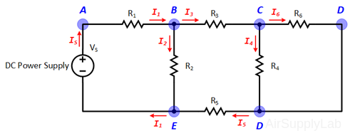
Data Table 3: Total Current on Each Node

Does the percentage error obtain seem reasonable In view of the accuracy of the DMM? - Using network reduction calculate the theoretical values of all of the branch currents (Using nominal values). Compare the branch current values so obtained with the values obtained by the DMM measurements (in step 5 table (d)). Record your results in the following table.

- The input resistance of the DMM is 10 MΩ. How much error will this input resistance result in? Will the loading effect of the DMM input resistance account for some of the experimental errors in step 4?
For this experiment, the percent error could not be reported as a fractional difference between a measured value and a theoretical value, because in this case the theoretical is 0 (it is the sum of the voltages around a closed-loop!). Therefore, the percent error (%err) can be calculated by comparing the measured sum of voltage drops to the average of the absolute values of the voltage drops along the closed-loop, that is:
\(\% err = \frac{{\sum v - 0}}{{\frac{{\sum v}}{n}}} \times 100\% \)
Exp #2: Superposition Theorem
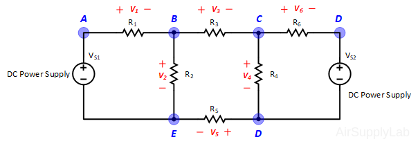 Figure 2: Exp #2 Circuit
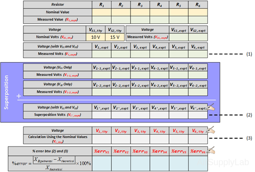
- Using the same circuit as for experiment 1, insert an additional power supply into the last loop as shown in Figure 2. Set VS1 to +10 V and VS2 to +15 V. Measure the values of VS1 and VS2 using a DMM and write the result in Data Table 2.

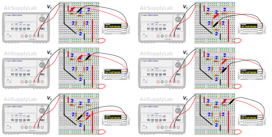
- Measure all branch voltages with a DMM (maximum place accuracy), Remember to keep track of algebraic signs. Record the value in Data Table 1.
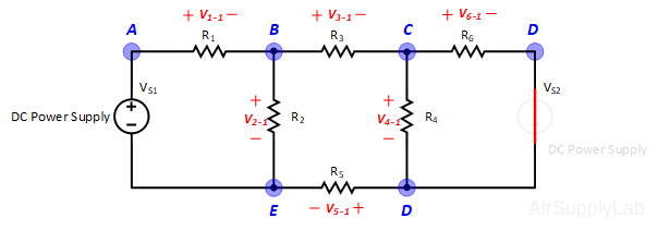
- Replace VS2 by a short-circuit. Measure all branch voltages. Record the measured voltages in the Data Table 2. Then put VS2 back into the circuit.
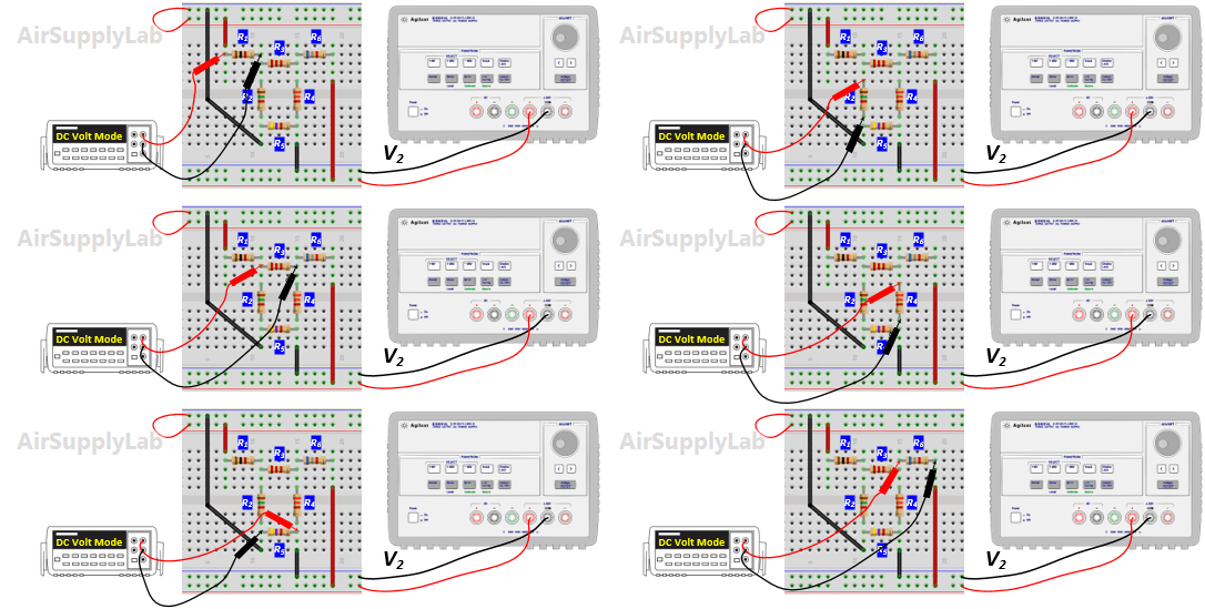
- Replace VS1 by a short-circuit. Measure all branch voltages and record the result in Data Table 2.
- From the above measurements verify that the superposition theorem is satisfied (Compare the result (1) and (2) in the Data table 2)
- Using network reduction and the superposition theorem calculate the theoretical values of all of the branch voltages in the circuit (using nominal values) and record the values in Data Table 2. Compare the calculated values with the measured values (Compare the result (2) and (3) in the Data Table 2).
Exp #3: Thevenin and Norton Theorem

Figure 3: Exp #3 Circuit
- Set up the circuit shown in Figure 3 using the same resistor network as used in exp #1. Adjust VS to +10 V. For RL, use a resistance substitution box.
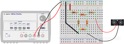
- Measure the output voltage VO for the following values of load resistance RL: 1 KΩ, 10 KΩ, 33 KΩ, and 100 KΩ. Measure VO with the maximum number of significant digits on the DMM.

- Replace RL with a short-circuit. Measure the voltage drop across R6 and calculate the short-circuit current from ISC = VR6 / R6.

- Disconnect RL from the circuit and measure the open-circuit output voltage VOC.

- With RL still out of the circuit, replace VS with a short-circuit. Measure the resistance RO that is seen looking back into the circuit using a DMM. Compare it with (VOC / ISC), which are measured on steps 3 and 4.

- Construct the Thevenin equivalent circuit using a resistance decade box for RO. Use a DMM for the adjustment of the resistance value of the resistance decade box so that it will be equal to RO.
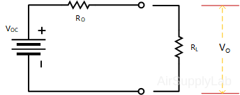
Figure 4: Thevenin Equivalent Circuit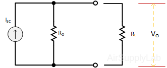
Figure 5: Norton Equivalent Circuit - Connect the load resistance RL to the Thevenin equivalent circuit. Measure the output voltage VO for the following values of load resistance RL: 1 KΩ, 10 KΩ, 33 KΩ, 100 KΩ, 330 KΩ. Compare the values of VO obtained here with the Thevenin equivalent circuit with the corresponding values obtained from the actual circuit.

