Lab 07: Basic Circuit and Divider Rules
Objective
- Become familiar with and organize Circuit Kit for the semester.
- Become familiar with a breadboard with the lab power supply and review the measurement of voltage, current, and resistance using a Digital Multimeter (DMM).
Equipment
 Breadboard
- Digital Multimeter (DMM)
- Power Supply
Background
Serial Circuit

The equivalent series resistance Rseries is the sum of the individual resistances: ${R_{series}} = \sum {{R_n}} $
Key properties of a series circuit are:
- the current through all components is the same.
- the voltages across all components must be added up to the source voltage, according to KVL:
$\sum {{V_n} = 0\; \Rightarrow \;{V_{source}} = {V_1} + {V_2} + {V_3}} $
Parallel Circuit

The equivalent parallel resistance Rparallel is given by: $\frac{1}{{{R_{parallel}}}} = \sum {\frac{1}{{{R_n}}}} $
Key properties of a parallel circuit are:
- the voltage across all components is the same.
- the current through all components must add up to the source current, according to KCL:
$\sum {{I_n} = 0\quad \Rightarrow \quad } {I_{source}} = {I_1} + {I_2} + {I_3}$
$\% Difference = \% diff = \frac{{\left| {Valu{e_1} - Valu{e_2}} \right|}}{{\left( {\frac{{Valu{e_1} + Valu{e_2}}}{2}} \right)}} \times 100\% $
Procedure
Exp #1: Connection Pattern of the Breadboard
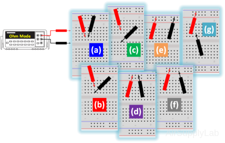
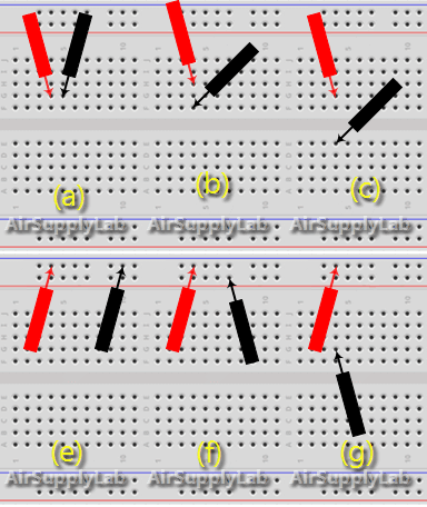
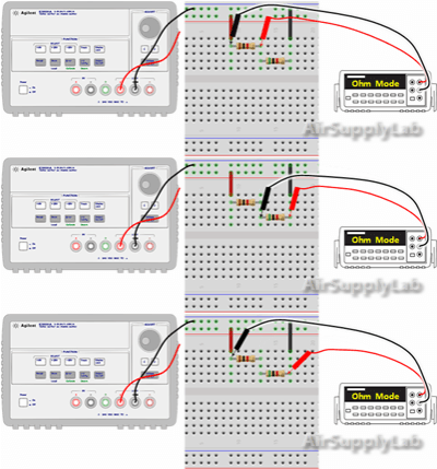
- Set the DMM to OHMS and the range to lowest resistance. Use jumper wires to make connections to the meter. Measure the continuity between different sets of pins to determine which groups of pins are connected and which are not. Lack of continuity will be read as an open circuit by the DMM.

- Connect the power supply to the breadboard posts. Use jumper cables to transfer the power from the posts to the breadboard pins labeled “+” and “−” at the top of the board. Measure the open-circuit voltages (vs) to confirm that the power was transferred.

- Set th power supply to provide an output of 10 V as read on the DMM.
- Disconnect the red wire from the power supply to the breadboard. Do not turn off the power supply.
Exp #2: Basic Series Measurements
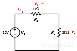
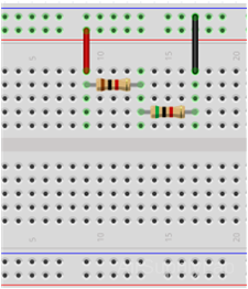
Construct the following series circuit on the breadboard, but do not connect the Power Supply.
Part 2A: Equivalent Serial Resistance
- Measure the actual values of each of your two resistors using the DMM.
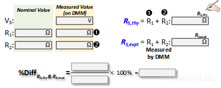
- Calculate the theoretical equivalent series resistance RS,thy using the measured resistor values.
- Measure the total resistance RS,expt of the two resistors (R1 + R2) using the DMM. Do not connect the power supply for this step.
- Use a percent difference to compare the theoretical (RS,thy) and experimental (RS,expt) values. How do they compare? How does the equivalent series resistance compare with that of the individual resistor values? Why?
Part 2B: Properties of a Series Circuit
Series Voltage
- Connect the power supply to the breadboard.
- Measure the voltage across each resistor. Record your values in table.
- Verify that KVL is satisfied around the path (VS=V1 + V2). From your data table is there a relationship between the resistor value and the voltage drop across the resistor? Explain your reasoning.

Series Current
- Energize the circuit and measure the current (I) using the ammeter.
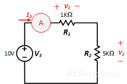
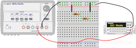
- Using the power supply voltage and the ammeter reading, calculate the equivalent series resistance RS,Ohm using Ohm's low. Use a percent difference to compare the RS,Ohm with RS,expt from Part 2A. How do they compare?

- Repeat Part 2B where the voltage has been increased to 30 V.
Set [+25V] to maximum positive 25 voltage , and [-25V] to negative 5 voltage. Then connect the power source from the positive and negative terminals on the power supply to get totally 30 V output.
Exp #3: Basic Parallel Measurements
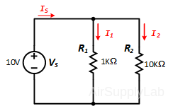
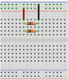
Construct the following parallel circuit but do not connect the power supply.
Part 3A: Equivalent Parallel Resistance
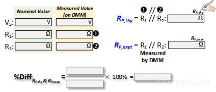
- Measure the actual values of each of your two resistors sing the DMM.
- Calculate the theoretical equivalent parallel resistance RP,thy using the measured resistor values.
- Measure the total parallel resistance RP,expt using a DMM. Do not connect the power supply for this step.
- Using percent difference to compare the theoretical (RP,thy) and experimental (RP,expt) values. How do they compare? How does the equivalent parallel resistance compare with that of the individual resistor values? Why?
Part 3B: Properties of a Parallel Circuit
Parallel Currents
- Measure the current through each resistor (I1, I2) and the current source (IS) with the DMM. Record your values in table
- Verify that KCL is satisfied (IS = I1 + I2).. From your data table, is there a relationship between the resistor value and the current through each resistor? Explain your reasoning.

Parallel Voltages
- Using the supply voltage (vS) and the current source (IS ), calculate the equivalent parallel resistance RP,Ohm using Ohm’s law. Use a percent difference to compare the RP,Ohm with RP,expt from Part 3A. How do they compare?
Questions
Challenge: Series and Parallel Combination Circuits
If you do not have the resistors (120 Ω, 240 Ω, and 560 Ω), then you can skip step (c) on both parts.
Part 1
- Design a circuit with two resistors (120 Ω and 240 Ω) connected in series, and place this series combination in parallel with a third resistor (560 Ω). Connect the entire resistor network to a 10.0 V power supply.
- Calculate the voltage across and the current through each of the three resistors. Record your calculations in a table.
- Measure the voltage across and the current through each resistor using the DMM. Record your measurements in a table. How do they compare with your calculation?
Part 2
- Design a circuit with two resistors (120 Ω and 240 Ω) connected in parallel, followed by a third resistor (560 Ω) in series. Connect this resistor combination to a 10.0 V power supply.
- Calculate the voltage across and the current through each of the three resistors. Record your calculations in a table.
- Measure the voltage across and the current through each resistor using the DMM. Record your measurements in a table. How do they compare with your calculation?
