Lab 06: PSpice Analysis of DC Circuits
Objective
- Use PSpice Circuit Simulator to check laboratory circuits and homework problems.
Equipment
- Cadence SPB/OrCAD 16.6 - PSpice or newer edition
Background
A DC circuit is a circuit in which the voltages of all independent voltage sources and the currents of all independent current sources have constant values. All of the currents and voltages of a DC circuit, including mesh currents and node voltages, have constant values. PSpice can analyze a DC circuit to determine the values of the node voltages and also the values of the currents in voltage sources. PSpice uses the name “Bias Point” to describe this type of analysis. The name “Bias Point” refers to the role of DC analysis in the analysis of a transistor amplifier.)
In this lab, we consider four examples. The first example illustrates the analysis of circuits containing independent sources while the second is dependent sources. The third illustrates the use of PSpice to check the node or mesh equations of a circuit to verify that these equations are correct. The final example uses PSpice to compare two DC circuits.
Procedure
- Hand Calculations: Solve the circuit analysis problem by using KVL, KCL, and Thevenin's theorem.
- Draw the Circuit Diagram: Describe the circuit using Schematics in the PSpice Capture. This description requires three activities:
- Place the circuit components in the Schematics workspace.
- Adjust the values of the circuit component parameters.
- Wire the circuit to connect the circuit components and add a 0 Volt ground (referenced ground).
- Simulation: Using PSpice to simulate the circuit.
- Results: Display the results of the simulation.
- Verify: Compare the simulation results with your calculations.
- Report: Write the answer to the circuit analysis problem.
Exp #1: DC Circuits Containing Independent Sources
Part 1A: Capturing and Simulating the DC Circuit
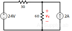
Apply the 6-step procedure to analyze the circuit shown as follows to determine the value of V6, which the voltage across the 6 Ω resistor.

Draw the above circuit in the PSpice Capture.
Part 1B: Verify that the simulation results are correct
Using simple circuit methods to calculate the result by hand calculation, and verify the result with the PSpice. Is the original circuit equivalent to the PSpice circuit? Use short concise sentences to explain your reasoning.
Exp #2: DC Circuits Containing Dependent Sources
PSpice can be used to analyze circuits that contain dependent sources. The PSpice symbols used to represent dependent sources are labeled as E, F, G, and H (see the table to the right) and are located in the analogy library.

Part 2A: Capturing and Simulate a CCCS Circuit
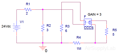
This example illustrates the analysis of a circuit that contains a dependent source. Particular attention is paid to preparing the circuit for analysis using PSpice. Suppose that a circuit containing a dependent source is:

An equivalent PSpice circuit would look like:

Part 2B: Verify that the simulation results are correct
Use simple circuit methods (hint: KCL at each node) to verify the results of v and i . Are the two circuits’ equivalent?
Exp #3: Mesh and Node Equations
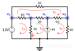
In this example, PSpice is used to check node and mesh equations of a circuit. Consider the circuit shown. A set of mesh currents has been labeled and the nodes of this circuit have been numbered.

The circuit can be represented by the following node and mesh equations:
Node Equations
\(\begin{array}{l}
23{v_b} - 12{v_c} = 36\\
- 55{v_b} + 21{v_c} - 6{v_d} = 0\\
- 6{v_c} + 26{v_d} = 180
\end{array}\)
Mesh Equations
\(\begin{array}{l}
17{i_1} - 8{i_2} - 2{i_3} - 5{i_4} = 0\\
- 8{i_1} + 11{i_2} - 3{i_3} = 12\\
- 7{i_1} - 3{i_2} + 5{i_3} + 11{i_4} = 0\\
- 4{i_2} + 3{i_3} + {i_4} = 0
\end{array}\)
The objective of this example is to use PSpice to determine if these equations are correct.
Part 3A: Formulating a circuit with PSpice
We have seen that PSpice will calculate the node voltages of a circuit such as the one shown above. The node equations can be checked by determining the values of the node voltages using PSpice and substituting those values into the node equations. PSpice does not calculate mesh currents, but it does calculate the currents in voltage sources. The mesh current i2 is the current through the 12 V voltage source. PSpice uses the passive convention for all elements, including voltage sources. The voltage source current that PSpice will report is the current direction from + to −. In this case, PSpice will report the value of –i2 rather than i2. Similarly, 0 V-voltage sources can be added to the circuit to measure the other mesh currents such as mesh currents i1, i3 and i4.
Part 3B: Verify that the simulation results are correct
One can verify the results in one of the following ways.
- Substitute the node voltages (mesh currents) from PSpice into the node equations (loop equations) and verify that they satisfy these equations.
- Solve the system of equations (for both Node and Mesh) using the matrix operations on your calculator and compare them to the PSpice results.
Exp #4: Challenge PSpice Circuit
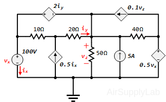
A dc circuit with dependent sources is shown. Use PSpice to find the values of ix, iy and vz.

Report
Turn in all PSpice circuits for each of the parts listed below:
- Exp #1: Determine the voltage V across the 6 Ω-resistor using simple circuit techniques and compare it to PSpice calculated value. How do they compare?
- Exp #2: Determine the voltage V across the 5 Ω-resistor and the current i through the 6 Ω-resistor using simple circuit techniques and compare it to PSpice calculated values. How do they compare?
- Exp #3: Use PSpice to determine the node voltages (Vb, Vc, Vd) and the mesh (or loop) currents (i1, i2, i3, i4). Substitute these values into the node equations and the mesh equations. Do the PSpice values satisfy these node and mesh equations?
- Exp #4: Use PSpice to determine that the controlling variables (ix, iy, Vz) and verify that the dependent source values are correct.
Capture your PSpice result and paste it on your report. Show your detailed calculations in the report, then compare your answers to the PSpice calculated values.