PSoC5LP Lab 04: Ultrasonic Module HC-SR04
Objective
- Measure distance using the HC-SR04 ultrasonic sensor.
- Understand the principles of ultrasonic echo-ranging.
Overview
Ultrasonic Module in Embedded Systems
Ultrasonic modules are commonly used in embedded systems for measuring distance, object detection, and other non-contact sensing applications. These modules leverage ultrasonic waves, which are sound waves with frequencies higher than the upper audible limit of human hearing, typically above 20 kHz. This background will cover ultrasonic theory, the working principle of ultrasonic modules, common types of ultrasonic sensors, and their applications in embedded systems.
Ultrasonic Theory
Ultrasonic waves are mechanical vibrations that propagate through a medium (such as air, water, or solid objects) in sound waves with frequencies beyond the human hearing range. Ultrasonic waves can be reflected, refracted, or absorbed depending on the material they interact with, making them useful for various sensing applications.
Key Characteristics:
- Frequency Range: Ultrasonic waves are typically those above 20 kHz, but industrial applications often use frequencies between 40 kHz and 400 kHz.
- Velocity of Sound: The speed at which ultrasonic waves travel through a medium depends on the medium's physical properties (density, temperature, etc.). For example, the speed of sound in air at 20°C is approximately 343 meters per second (m/s).
- Reflection: Ultrasonic waves reflect off surfaces, and the time taken for the wave to return can be used to calculate the distance of an object.
- Wavelength: The wavelength of the ultrasonic wave determines its ability to detect small objects; higher frequencies have shorter wavelengths, which allows for the detection of smaller objects.
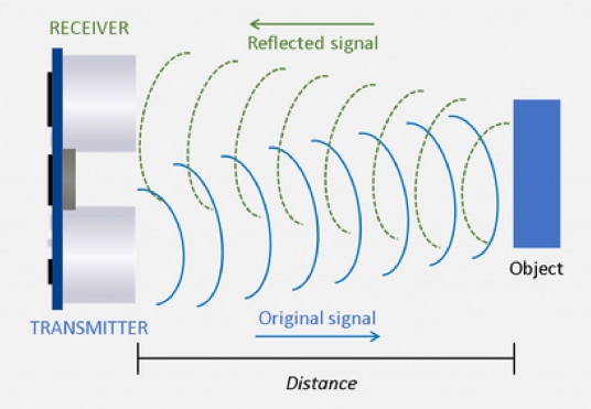
Working Principle of Ultrasonic Modules
In embedded systems, ultrasonic modules generally function by emitting an ultrasonic pulse and then measuring the time it takes for the echo to return after hitting an object (echo-ranging technique). The time-of-flight (TOF) of the sound wave is used to calculate the distance to the object.
Working Steps:
- Emission of Ultrasonic Pulse: The module sends out a short burst of ultrasonic waves (often 40 kHz) using a piezoelectric transducer.
- Wave Propagation: The waves travel through the air, reflecting off any object in their path.
- Echo Reception: The transducer switches to "receive" mode and detects the reflected waves (echo).
- Time Measurement: The embedded system records the time interval between the pulse's emission and the echo's reception.
- Distance Calculation: Based on the speed of sound and the time delay, the distance to the object can be calculated using the formula:
$Distance = {{Speed Of Sound \times Time Of Flight} \over 2}$
The division by 2 accounts for the wave traveling to the object and back.
Common Components:
- Transmitter and Receiver: In some modules, there are separate units for transmission and reception, while in others, a single transducer is used for both purposes.
- Signal Processor: Embedded systems usually include a microcontroller to process the received signal and calculate the distance.
- Voltage Regulator: To ensure stable operation, modules often include a voltage regulator.
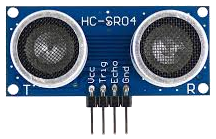
Common Ultrasonic Module: HC-SR04
One of the most commonly used ultrasonic modules in embedded systems is the HC-SR04. It operates at a frequency of 40 kHz and can measure distances from 2 cm to 400 cm with an accuracy of about 3 mm.
Applications of Ultrasonic Modules in Embedded Systems
Ultrasonic modules are widely used in various applications in embedded systems. Their ability to measure distance, detect objects, and work in various environmental conditions makes them versatile. Here are some key applications:
Distance Measurement
Ultrasonic modules are primarily used to measure distances in embedded systems. Typical applications include:
- Obstacle Detection in Robotics: Robots often use ultrasonic sensors to detect obstacles in their path, allowing them to navigate safely.
- Parking Assistance Systems: Cars use ultrasonic sensors in parking assistance systems to detect nearby objects and provide alerts to drivers.
- Level Sensing: Ultrasonic modules measure the level of liquids or solids in tanks by calculating the distance from the sensor to the material's surface.
Object Detection
The ability of ultrasonic sensors to detect objects makes them valuable in a range of industries:
- Security Systems: Ultrasonic modules are used in intrusion detection systems to detect unauthorized access in secured areas.
- Industrial Automation: Automated manufacturing systems use ultrasonic modules to detect the presence of parts or obstacles on conveyor belts.
- Agriculture: In agricultural robots, ultrasonic sensors can help detect objects such as plants, animals, or farm machinery.
Proximity Sensing
Ultrasonic sensors are widely used for proximity detection in various embedded applications:
- Mobile Devices: Some smartphones use ultrasonic sensors for proximity detection, such as turning off the display during a call when the phone is near the user's ear.
- Touchless Switches: Ultrasonic sensors enable touchless activation of smart home systems' lights, doors, or appliances by detecting hand movements within a specific range.
Autonomous Vehicles
In autonomous vehicles (drones, self-driving cars), ultrasonic sensors assist in obstacle avoidance, especially in close-range scenarios. These sensors work alongside other technologies like cameras and LIDAR to ensure the vehicle's environment is accurately mapped and navigated.
Medical Applications
Ultrasound technology is also applied in medical devices for non-invasive diagnostics, imaging (such as ultrasound scans), and therapy. While not directly related to embedded systems, ultrasound imaging relies on the same principles of ultrasonic wave propagation and reflection.
Advantages and Limitations of Ultrasonic Modules
Advantages:
- Non-Contact Measurement: Ultrasonic modules can measure distance and detect objects without physical contact, reducing wear and tear.
- Works in All Lighting Conditions: Unlike infrared sensors, ultrasonic sensors are not affected by lighting conditions, making them suitable for outdoor applications.
- Wide Range of Applications: Ultrasonic sensors can work in various media, such as air, water, and even certain solids.
- High Accuracy: Ultrasonic modules provide accurate measurements, typically within a few millimeters for common modules like the HC-SR04.
Limitations:
- Environmental Sensitivity: The performance of ultrasonic modules can be affected by environmental conditions such as temperature, humidity, and wind, which influence the speed of sound.
- Limited Detection Range: Ultrasonic modules typically have a limited range (up to several meters), which may not be sufficient for some applications.
- Surface Limitations: Some surfaces (e.g., soft materials) absorb sound rather than reflect it, leading to inaccurate readings.
- Beam Divergence: The sound beam emitted by an ultrasonic sensor can spread out, which might cause issues in detecting small or narrow objects.
Ultrasonic modules are crucial in embedded systems, offering reliable and accurate distance measurement and object detection. The versatility of these sensors, combined with their ability to operate in various environments and detect a wide range of materials, makes them invaluable in fields ranging from robotics and automation to automotive and medical applications. Developers can build multiple applications that enhance automation, safety, and convenience by understanding ultrasonic theory and leveraging the technology in embedded systems.
Required Reading Materials
- Lesson KB 06: Interfacing Character LCD Display Module with PSoC
- HC-SR04 Ultrasonic Module Datasheet
- Wikipedia: Speed of sound
- PSoC Creator Component Datasheet:
Required Components
| HC-SR04 Ultrasonic Module | × 1 | |
| Character LCD Module | × 1 | |
| 10 KΩ Potentiometer | × 1 |
Circuit / Schematic
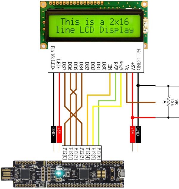
- Connection for Character LCD Module

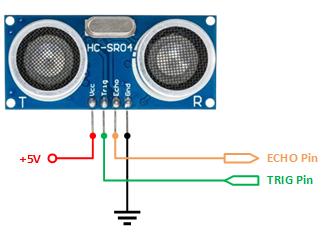
- Connection for HC-SR04 Ultrasonic module
Procedure
Creating a New Project
- Launch PSoC Creator.
- Got to File ➤ Open Project ➤ Project/Workspace.
- Open the PSoC5LP workspace in the EE4450 folder.
- After PSoC Creator opens the workspace, right-click on Workspace 'PSoC5LP' in the Workspace Explorer and select Add ➤ New Project...
- Select the correct PSoC5LP device model number, use the "Empty schematic" template, and enter the project name 04_Ultrasonic.
Adding PSoC Creator Components
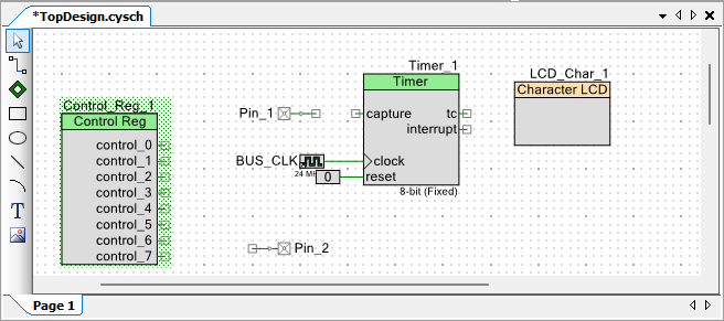
Follow these detailed steps to add components to the PSoC Creator project by modifying the TopDesign.cysch schematic file::
- Add a Character LCD component:
- Navigate to the Display catalog in the component selection panel.
- Drag and drop the
 Character LCD onto the schematic.
- Add a Timer component:
- Navigate to the Digital ➤ Functions catalog in the component selection panel.
- Drag and drop the Timer onto the schematic.
- Add a Digital Input Pin:
- Navigate to the Ports and Pins catalog in the component selection panel.
- Drag and drop the
 Digital Input Pin onto the schematic.
- Add a Digital Output Pin:
- Similarly, go to the Ports and Pins catalog.
- Drag and drop the Digital Output Pin onto the schematic.
- Add a Control Register:
- Navigate to the Digital ➤ Registers catalog in the component selection panel.
- Drag and drop the Character LCD onto the schematic.
Following these steps, you will successfully add a Character LCD, Timer, Digital Input Pin, Digital Output Pin, and Control Register component to the schematic in PSoC Creator.
Configure the Components
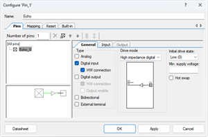
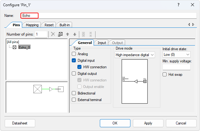
- Config the Digital Input Pin (Pin_1):
- Click on the Pin_1 component in the schematic.
- Rename the component to Echo to reflect its connection to the ultrasonic's echo pin.
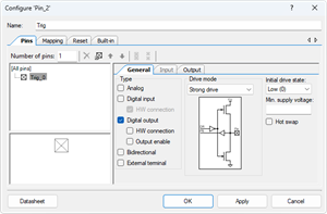
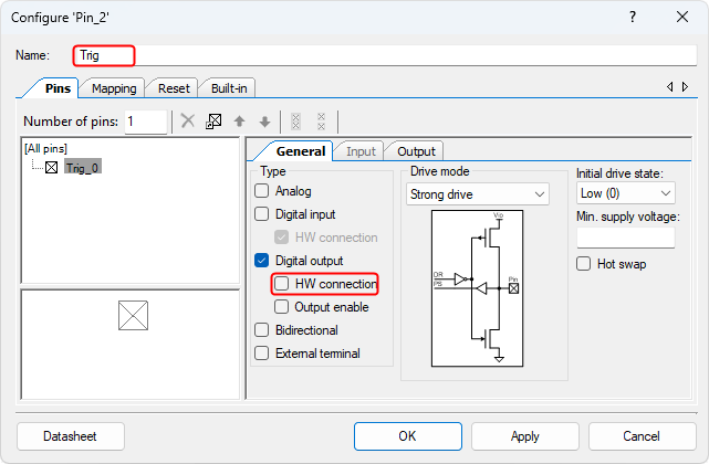
- Config the Digital Output Pin (Pin_2):
- Click on the Pin_2 component in the schematic.
- Rename the component to Trig to represent its connection to the ultrasonic sensor's trig pin.
- Uncheck the box for ☐ HW connection to disable the hardware connection. This step ensures that the pin will be controlled manually in the software.
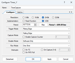
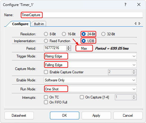
- Config the Timer (Timer_1):
- Click on the Timer_1 component in the schematic.
- Rename the component to TimerCapture.
- Change the Implementation to UDB (Universal Digital Block).
- Select the Resolution to 24-bit.
- Click the Max button to set the maximum period value automatically.
- Set the Trigger Mode to Rising Edge. This setting ensures that the timer starts on a rising signal edge.
- Set the Capture Mode to Falling Edge, which ensures that the timer captures values when the falling edge of the signal occurs.
- Change the Run Mode to the One Shot. This mode ensures that the timer runs once per trigger event, capturing a single measurement
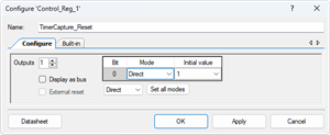
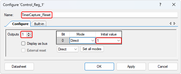
- Config the Control Register (Control_Reg_1):
- Click on the Control_Reg_1 component in the schematic.
- Rename the component to TimerCapture_Reset.
- Change the Outputs to 1.
- Change the Initial value to 1. This ensures the reset control register is initialized properly.
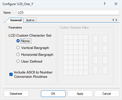
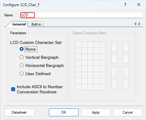
- Config the Character LCD (LCD_Char_1):
- Click on the LCD_Char_1 component in the schematic.
- Rename the component to LCD for clarity and ease of identification.
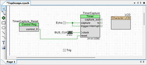
Wiring
- Delete the existing Logic 0 component connected to the TimerCapture module's reset pin. Delete this Logic 0 component to allow for a new connection.
- Connect a wire from the control_0 pin on the TimerCapture_Reset module to the reset pin of the TimerCapture module. This will enable the reset functionality to be controlled by the TimerCapture_Reset module.
- Connect the input Echo pin to the capture and trigger pins of the TimerCapture module. This will allow the TimerCapture module to detect the trigger signal and capture the timing based on the echo response.
- A detailed connection diagram illustrating the wiring setup, including the reset connection and pin wiring, is provided below. Use this diagram to verify your connections and ensure everything is correctly wired according to the system design.

Pin Assignment
| Device | Port.Pin | Direction | Drive Mode |
|---|---|---|---|
Template Firmware Code
main.c
#include "project.h"
#include <stdio.h>
#include <stdlib.h>
#include <stdint.h>
#include <stdbool.h>
#include <string.h>

float measureDistance();

int main(void)
{
    float distance_cm;          // Variable to store the calculated distance in centimeters

    CyGlobalIntEnable; /* Enable global interrupts. */

    // Initialization and startup code
    TimerCapture_Start();                   // Start the timer used for capturing pulse width
    TimerCapture_Reset_Write(1);            // Set reset pin to initialize the timer
    Trig_Write(0);                          // Ensure the Trig pin is initially low

    LCD_Start();                            // Initialize the LCD display
    LCD_ClearDisplay();                     // Clear any previous data on the LCD
    LCD_Position(0,0);                      // Set cursor to the first row, first column
    LCD_PrintString("PSoC5LP Ultrasonic");  // Display course information on the first row
    LCD_Position(1,0);                      // Set cursor to the second row, first column
    LCD_PrintString("HC-SR04");             // Display "HC-SR04" label on the second row
    CyDelay(2000);                          // Delay for 2 seconds to keep the initial message displayed

    for(;;)
    {
        // Measure the distance using the ultrasonic sensor
        distance_cm = measureDistance();
        if (measureDistance < 0) {       // Check if the distance measurement is out of range
            // Display "Out of range" message on the LCD screen

        } else {
            // Display the measured distance in centimeters on the LCD screen

        }
        CyDelay(500);                       // Delay for 500 milliseconds before the next measurement
    }
}
//------------------------------------------------------------------------------
// Function to measure distance using the HC-SR04 Ultrasonic sensor
float measureDistance()
{
    float distance_cm;                      // Variable to store the calculated distance in centimeters
    float pw;                               // Variable to store pulse width

    // Code to trigger ultrasonic pulse and measure pulse width should be here

    return distance_cm;                     // Return the calculated distance
}
/* [] END OF FILE */
Exercises
Exp #01: Measure the distance in centimeters
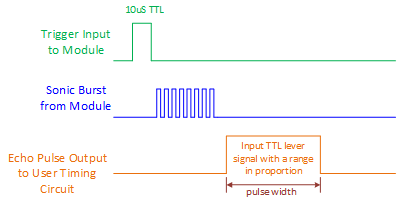
Timing Diagram for HC-SR04 Ultrasonic Module
Based on the Timing Diagram above, implement the measureDistance() function. The steps as follows:
function measureDistance()
    Send a 10 µs pulse on Trig pin

    Disable the Timer reset pin

    LOOP:
        Check timer status register
        If status.CAPTURE_FLAG is set
            Read the Capture value from Timer's Capture register
            Calculate pulse width
            Calculate distance (cm) based on pulse width
            Set distance to calculated value
            Exit LOOP

        Else if status.TC_FLAG is set (timeout condition)
            Set distance to -1 (out-of-range)
            Exit Loop
    REPEAT LOOP

    Enable the Timer reset pin
    Return distance
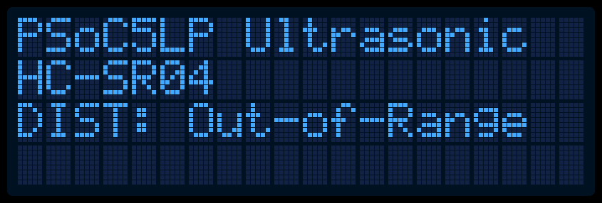
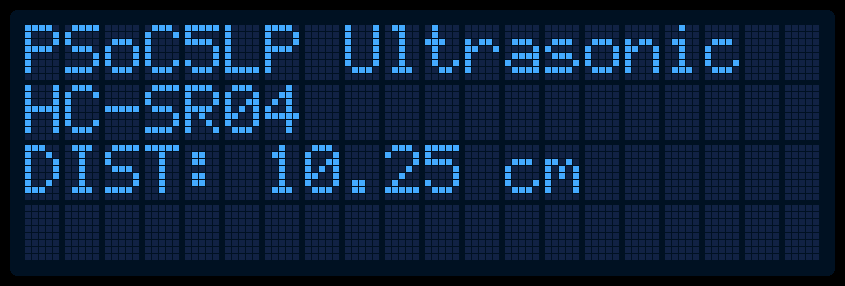
Example LCD Screen Layouts as below: