Lesson 00 - Understanding the Raspberry Pi Boards And Accessories
0.1 Raspberry Pi Hardware
Hardware Comparisons
Hardware Comparison
| Family | Board | Model | CPU | Memory | Form Factor | Network | GPIO | Power | Released |
|---|---|---|---|---|---|---|---|---|---|
| Raspberry Pi 1 |  |
B+ | BCM2835 (Single-Core 700MHz) |
512MB | Standard (85.60 × 56.5 mm) | 100 Base Ethernet | 40-Pin | 2014 | |
 |
A+ | 512MB | Compact (65 × 56.5 mm) | None | 40-Pin | via μUSB | 2014 | ||
| Raspberry Pi 2 | B | BCM2836 / 7 | 1GB | Standard (85.60 × 56.5 mm) | Yes | 40-Pin | 2015 | ||
| Raspberry Pi Zero | Ultra-Compact (65 × 30 mm) | 2015 | |||||||
| W / WH | BCM2835 (Single-Core 1 GHz) |
512MB RAM | Ultra-Compact (65 × 30 mm) | 802.11 b/g/n WiFi Bluetooth 4.1/BLE |
2017 | ||||
 |
2W | RP3A0 (Arm Cortex-A53 1GHz) |
512GB SDRAM | Ultra-Compact (65 × 30 mm) | 2.4GHz 802.11 b/g/n WiFi Bluetooth 4.2/BLE |
5.1V/2.5A DC via μUSB | 2021 | ||
| Raspberry Pi Pico | Pico | RP2040 Arm Cortex-M0+ (Dual-Core 133MHz) |
264KB SRAM | Pico (21 × 51 mm) | 40-Pin | 2021 | |||
| Pico W | RP2040 Arm Cortex-M0+ (Dual-Core 133MHz) |
264KB SRAM | Pico (21 × 51 mm) | 2.4GHz 802.11n WiFi Bluetooth 5.2 |
2022 | ||||
| Raspberry Pi 3 | B | BCM2837 (Quad-Core 1.2GHz) |
1GB SDRAM | Standard (85.60 × 56.5 mm) | WiFi Bluetooth BLE |
40-Pin | 5.1V/2.5A DC via μUSB | 2016 | |
 |
A+ | BCM2837B0 (Quad-Core 1.4GHz) |
512MB LPSSR2 | Compact (65 × 56.5 mm) | Dual-band 802.11ac WiFi Bluetooth 4.3/BLE |
40-Pin | 5V/2.5A DC via μUSB | 2018 | |
 |
B+ | BCM2837B0 Cortex-A53 (1.4 GHz) |
1GB LPDDR2 | Standard (85.60 × 56.5 mm) | Gigabit Ethernet over USB2 Dual-Band 802.11ac WiFi Bluetooth 4.2/BLE |
40-Pin | 5V/2.5A DC via μUSB | 2018 | |
| Raspberry Pi 4 |  |
B/A | BCM2711 (Quard-Core 1.8GHz) |
1GB / 2GB / 4 GB / 8GB | Standard (85.60 × 56.5 mm) | Gigabit Ethernet Dual-band 802.11ac WiFi Bluetooth 5.0/BLE |
40-Pin | 5V/3A DC via USB-C | 2019: 1GB / 2GB / 4GB 2020: 8GB |
| 400 | BCM2711 (Quard-Core 1.8GHz) |
4 GB | Keyboard (285 × 122 × 23 mm) | Gigabit Ethernet Dual-band 802.11ac WiFi Bluetooth 5.0, BLE |
40-Pin | 5V/ DC via USB | 2020 | ||
| Raspberry Pi 5 |  |
BCM2712 (Quad-Cord 2.4GHz) |
4GB 8GB |
Standard (85.60 × 56.5 mm) | Gigabit Ethernet Dual-band 802.11ac WiFi |
40-Pin | 5V/5A DC via USB-C | 2023 |
Pi Pico
Raspberry Pi Pico
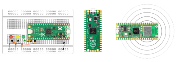
There are two versions of Pi Pico W boards:
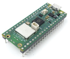
Raspberry Pi Pico WH with PRE-SOLDERED male headers by Raspberry Pi is breadboard friendly, plug and use!
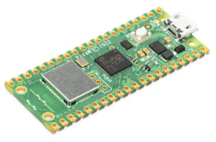
Raspberry Pi Pico W without header, SMD-friendly
Specification
- CPU: RP2040 Dual-core ARM Cortex-M0+ processor, flexible clock running up to 133 MHz
(microcontroller chip designed by Raspberry Pi in the UK) - RAM: 264kB on-chip SRAM
- Flash: 2MB onboard Q-SPI flash
- Wifi: 2.4GHz 802.11n wireless LAN (Raspberry Pi Pico W and WH only)
- Bluetooth: Bluetooth 5.2 (Raspberry Pi Pico W and WH only)
- 26 multifunction GPIO pins, including 3 analog inputs
- 2 × UART, 2 × SPI controllers, 2 × I2C controllers, 16 × PWM channels
- 1 × USB 1.1 controller and PHY, with host and device support
- 8 × Programmable I/O (PIO) state machines for custom peripheral support
- Supported input voltage 1.8 ~ 5.5V DC
- Operating temperature -20°C to +85°C (Raspberry Pi Pico and Pico H); -20°C to +70°C (Raspberry Pi Pico W and Pico WH)
- The castellated module allows soldering directly to carrier boards (Raspberry Pi Pico and Pico W only)
- Drag-and-drop programming using mass storage over USB
- Low-power sleep and dormant modes
- Accurate on-chip clock
- Temperature sensor
- Accelerated integer and floating-point libraries on-chip
- 21 mm × 51 mm form factor
The Raspberry Pi Pico series is a range of tiny, fast, and versatile boards built using RP2040, the flagship microcontroller chip designed by Raspberry Pi in the UK.
Pi Zero
Raspberry Pi Zero W
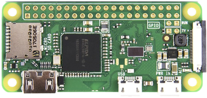
Specification
- CPU: Broadcom BCM2835 1GHz Single-core 64-bit ARM11 CPU
- RAM: 512MB SDRAM
- WiFi: 2.4GHz 802.11 b/g/n wireless LAN
- Bluetooth: Bluetooth 4.1, Bluetooth Low Energy (BLE), onboard antenna
- Mini HDMI port and micro USB On-The-Go (OTG) port
- microSD card slot
- CSI-2 camera connector
- HAT-compatible 40-pin header footprint (unpopulated)
- H.264, MPEG-4 decode (1080p30); H.264 encode (1080p30)
- OpenGL ES 1.1, 2.0 graphics
- 5.1V/2.5A DC via micro USB power
- Composite video and reset pins via solder test points
- Dimension: 65mm x 30mm
Raspberry Pi Zero 2 W
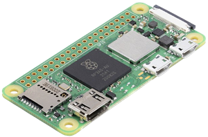
Specification
- CPU: RP3A0-AU SiP (BCM2710A1) 1GHz Quad-core 64-bit ARM Cortex-A53 CPU
- RAM: 512MB LPDDR2
- WiFi: 2.4GHz 802.11 b/g/n wireless LAN
- Bluetooth: Bluetooth 4.2, Bluetooth Low Energy (BLE), onboard antenna
- Mini HDMI port and micro USB On-The-Go (OTG) port
- microSD card slot
- CSI-2 camera connector
- HAT-compatible 40-pin header footprint (unpopulated)
- H.264, MPEG-4 decode (1080p30); H.264 encode (1080p30)
- OpenGL ES 1.1, 2.0 graphics
- 5.1V/2.5A DC via micro USB power
- Composite video and reset pins via solder test points
- Dimension: 65mm x 30mm
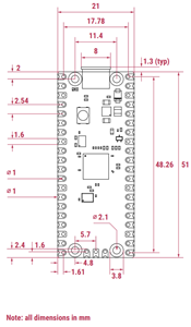
Dimensions: (All dimensions in mm)
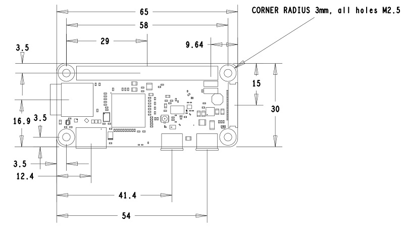
Pi 3
Raspberry Pi 3 Model B+
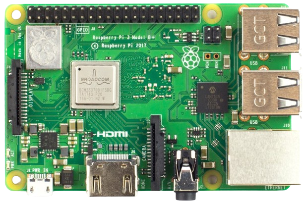
Specification
The Raspberry Pi 3 Model B+ is the final Raspberry Pi 3 range revision.
- CPU: Broadcom BCM2837B0 Quad-Core Cortex-A53 (ARMv8) 64-bit SoC @ 1.4GHz
- GPU: VideoCore IV
- RAM: 1GB LPDDR2 SDRAM
- WiFi/Bluetooth: 2.4GHz and 5GHz IEEE 802.11.b/g/n/ac wireless LAN, Bluetooth 4.2, BLE
- Ethernet: Gigabit Ethernet over USB 2.0 (maximum throughput 300 Mbps)
- GPIO: Extended 40-pin GPIO header
- HDMI: Full-size HDMI
- USB Port: 4 USB 2.0 ports with up to 1.2A output
- CSI camera port for connecting a Raspberry Pi camera
- DSI display port for connecting a Raspberry Pi touchscreen display
- 4-pole stereo output and composite video port
- Micro SD port for loading your operating system and storing data
- 5V/2.5A DC power input via micro USB
- Power-over-Ethernet (PoE) support (requires separate PoE HAT)
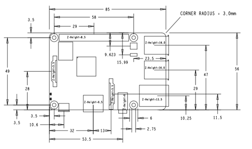
Dimensions: (All dimensions in mm)
Pi 4
Raspberry Pi 4 Model B
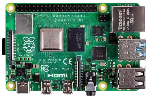
The Raspberry Pi 4 is a versatile and powerful single-board computer developed by the Raspberry Pi Foundation and released in June 2019. It marked a significant upgrade from its predecessors, featuring numerous enhancements in performance, connectivity, and capabilities. Key features of the Raspberry Pi 4 include:
- CPU: Broadcom BCM2711, Quad-core Cortex-A72 (ARM v8) 64-bit SoC @ 1.8GHz
- GPU: VideoCore VI @ 500 Mhz, supporting OpenGL ES 3.0
- 1GB, 2GB, 4GB, or 8GB LPDDR4-3200 SDRAM (depending on model)
- 2.4 GHz and 5.0 GHz IEEE 802.11ac wireless, Bluetooth 5.0, BLE
- Gigabit Ethernet
- 2 USB 3.0 ports; 2 USB 2.0 ports.
- Raspberry Pi standard 40-pin GPIO header (fully backward compatible with previous boards)
- 2 × micro-HDMI® ports (up to 4kp60 supported)
- 1 × 2-lane MIPI DSI display port
- 1 × 2-lane MIPI CSI camera port
- 4-pole stereo audio and composite video port
- H.265 (4kp60 decode), H264 (1080p60 decode, 1080p30 encode)
- OpenGL ES 3.1, Vulkan 1.0
- Micro-SD card slot for loading operating system and data storage
- 5V/3A DC via USB-C connector, or 5V/3A DC via GPIO header
- Power over Ethernet (PoE) enabled (requires separate PoE HAT)
- Operating temperature: 0 – 50 ºC ambient
The Raspberry Pi 4 is widely used for various applications, from educational tools and DIY projects to home automation, media centers, and even as a lightweight desktop computer. Its affordability, flexibility, and robust community support make it popular for hobbyists, educators, and professionals.
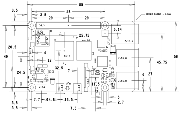
Dimensions:
Pi 5
Raspberry Pi 5
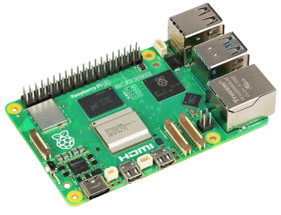
The Raspberry Pi 5 is the latest and most advanced single-board computer in the Raspberry Pi series, developed by the Raspberry Pi Foundation. It builds upon the success of previous models, introducing significant performance enhancements and new features to cater to a wide range of applications. Here are the detailed specifications and features of the Raspberry Pi 5:
Specification
- CPU: Broadcom BCM2712 2.4GHz quad-core 64-bit Arm Cortex-A76 (ARM v8) CPU, with cryptography extensions, 512KB per-core L2 caches and a 2MB shared L3 cache
- GPU: VideoCore VII GPU @ 800 MHz, supporting OpenGL ES 3.1, Vulkan 1.2
- Dual 4Kp60 HDMI display output with HDR support
- 4Kp60 HEVC (H.265) Hardware decoder
- LPDDR4X-4267 SDRAM (4GB, 8GB, and 16GB SKUs available at launch)
- Dual-band 802.11ac Wi-Fi
- Bluetooth 5.0 / Bluetooth Low Energy (BLE)
- microSD card slot, with support for high-speed SDR104 mode
- 2 × USB 3.0 ports, supporting simultaneous 5Gbps operation
- 2 × USB 2.0 ports
- Gigabit Ethernet, with PoE+ support (requires separate PoE+ HAT)
- 2 × 4-lane MIPI camera/display transceivers
- PCIe Gen 2.0 x1 interface for fast peripherals (requires separate M.2 HAT or other adapter)
- Dedicated Port:
- UART Connector
- RTC External Battery Connector
- Cooler Fan Connector
- 5V/5A DC power via USB-C, with Power Delivery support
- Raspberry Pi standard 40-pin header
- Real-time clock (RTC), powered by an external battery
- Power button
The Raspberry Pi 5 represents a significant leap forward in the capabilities of the Raspberry Pi platform, making it an excellent choice for education, DIY projects, home automation, media centers, and even as a low-cost desktop replacement. Its combination of high performance, versatile connectivity, and extensive community support continues to make it a popular and powerful tool for many users.
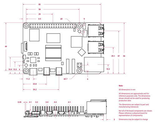
Dimensions:
0.2 Pi Board Pinout
Pi Pico Pinout
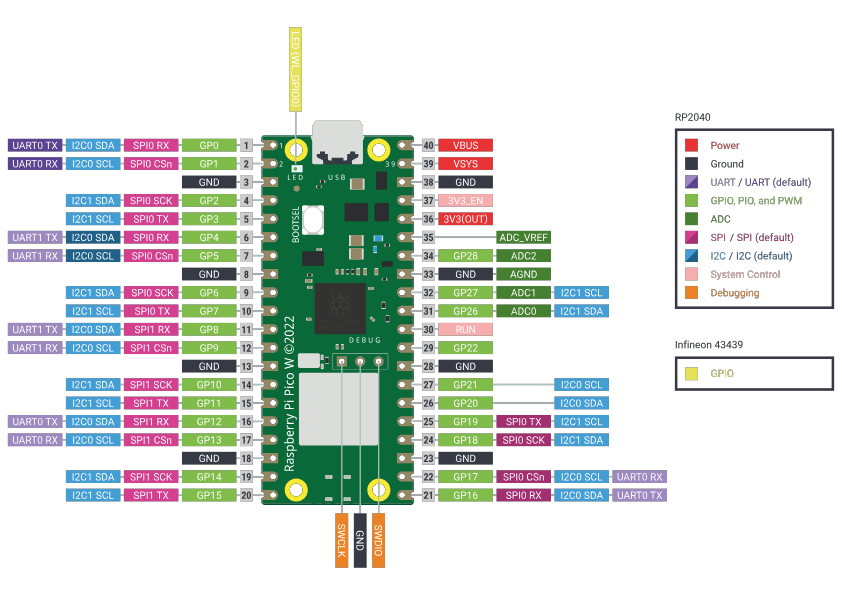
Pi 3/4/5 Pinout

| BCM | wPi | Name | Mode | Pin Header | Mode | Name | wPi | BCM | |||
|---|---|---|---|---|---|---|---|---|---|---|---|
| 3.3V | 1 | 2 | 5V | ||||||||
| 2 | 8 | GPIO 2 / I2C1.SDA | Pull-up Resistor | 3 |  |
 |
4 | 5V | |||
| 3 | 9 | GPIO 3 / I2C1.SCL | Pull-up Resistor | 5 |  |
 |
6 | GND | |||
| 4 | 7 | GPIO 4 / GPCLK0 | 7 |  |
 |
8 | UART.TxD / GPIO 14 | 15 | 14 | ||
| GND | 9 |  |
 |
10 | UART.RxD / GPIO 15 | 16 | 15 | ||||
| 17 | 0 | GPIO 17 / SPI1.CE1 | 11 |  |
 |
12 | SPI1.CE0 / PCM CLK / GPIO 18 | 1 | 18 | ||
| 27 | 2 | GPIO 27 | 13 |  |
 |
14 | GND | ||||
| 22 | 3 | GPIO 22 | 15 |  |
 |
16 | GPIO 23 | 4 | 23 | ||
| 3.3V | 17 |  |
 |
18 | GPIO 24 | 5 | 24 | ||||
| 10 | 12 | GPIO 10 / SPI0.MOSI | 19 |  |
 |
20 | GND | ||||
| 9 | 13 | GPIO 9 / SPI0.MISO | 21 |  |
 |
22 | GPIO 25 | 6 | 25 | ||
| 11 | 14 | GPIO 11 / SPI0.SCLK | 23 |  |
 |
24 | SPI.CE0 / GPIO 8 | 10 | 8 | ||
| GND | 25 |  |
 |
26 | SPI.CE1 / GPIO 7 | 11 | 7 | ||||
| 0 | 30 | GPIO 0 / EEPROM I2C0.SDA | 27 |  |
 |
28 | EEPROM I2C0.SCL / GPIO 1 | 31 | 1 | ||
| 5 | 21 | GPIO 5 / GPCLK1 | 29 |  |
 |
30 | GND | ||||
| 6 | 22 | GPIO 6 / GPCLK2 | 31 |  |
 |
32 | PWM0 / GPIO 12 | 26 | 12 | ||
| 13 | 23 | GPIO 13 / PWM 1 | 33 |  |
 |
34 | GND | ||||
| 19 | 24 | GPIO19 / PCM FS / SPI1.MISO | 35 |  |
 |
36 | SPI1.CE2 / GPIO 16 | 27 | 16 | ||
| 26 | 25 | GPIO 26 | 37 |  |
 |
38 | SPI1.MOSI / PCM DIN / GPIO 20 | 28 | 20 | ||
| GND | 39 |  |
 |
40 | SPI1.SCLK / PCM DOUT / GPIO 21 | 29 | 21 | ||||
5V Power
5V Power
The 5V power pins on the Raspberry Pi board are directly linked to the Pi's power input and can deliver the full supply current of your mains adapter minus the amount used by the Pi itself.
Using a reliable power supply, like the official Pi adapter, you can typically draw about 1.5A. However, this may vary depending on the Pi model and adapter. An external power supply is recommended for high-current devices, such as LED panels, long LED strips, or motors.
3.3 V Power
3.3 V Power
Thanks to an integrated switching regulator, all Raspberry Pi models from the B+ onward can provide up to 500mA on the 3.3V pins. While it might be possible to draw more current, the actual limits are not well-documented or extensively tested, so 500mA is recommended as a safe guideline.
The 3.3V supply pin on the early Raspberry Pi models had a maximum available current of only 50mA.
For powering 3.3V projects, it is recommended to use the 5V supply in combination with a 3.3V regulator.
Ground
Ground
The Ground pins on the Raspberry Pi are all electrically connected, so you can use any of them when wiring up a voltage supply.
It's usually best to choose the Ground pin that is most convenient or closest to your other connections for a tidier and easier setup. Alternatively, select the one nearest to the supply pin you're using.
For example, when using the SPI connections, it’s advisable to use Physical Pin 17 for 3.3V and Physical Pin 25 for ground, as these are conveniently located next to the key pins for SPI0.
I2C
I2C — Inter-Integrated Circuit
GPIO 2 and GPIO 3: These pins on the Raspberry Pi are designated as I2C1 pins, enabling two-wire communication with a variety of external sensors and devices. This makes them essential for interfacing with components that require I2C communication.
Pull-up Resistors: The I2C pins (GPIO 2 and GPIO 3) include fixed 1.8 kΩ pull-up resistors to 3.3V. Due to these built-in pull-ups, these pins are not suitable for general-purpose I/O where the pull-up might interfere with the operation.
Multi-Drop Bus: I2C is a multi-drop bus, meaning that multiple devices can be connected to the same two I2C pins. Each device must have a unique I2C address to communicate properly on the bus.
Verifying I2C Addresses: You can verify the addresses of connected I2C peripherals with the following commands:
sudo apt-get install i2c-tools
sudo i2cdetect -y 1
These commands will scan the I2C bus and display the addresses of any connected devices.
Accessing I2C in Python: To interact with I2C devices in Python, you can use the smbus library. Here's an example of how to write data to a device:
import smbus

DEVICE_BUS = 1
DEVICE_ADDR = 0x15
bus = smbus.SMBus(DEVICE_BUS)
bus.write_byte_data(DEVICE_ADDR, 0x00, 0x01)
GPIO 0 and GPIO 1 (Pin 27 & 28): These pins can be used as an alternate I2C bus (I2C0). However, they are typically reserved by the system for reading the HAT EEPROM, which contains configuration information for add-on boards.
SPI
SPI — Serial Peripheral Interface
SPI0 Pins: The primary SPI bus (SPI0) uses the following GPIO pins:
- GPIO 7 (CE1)
- GPIO 8 (CE0)
- GPIO 9 (MISO)
- GPIO 10 (MOSI)
- GPIO 11 (SCLK)
SPI1 Pins: The secondary SPI bus (SPI1) uses these GPIO pins:
- GPIO 16 (CE2)
- GPIO 17 (CE1)
- GPIO 18 (CE0)
- GPIO 19 (MISO)
- GPIO 20 (MOSI)
- GPIO 21 (SCLK)
Four-Wire Serial Bus: SPI is known as a four-wire serial bus, consisting of:
- MISO (Master In Slave Out)
- MOSI (Master Out Slave In)
- SCLK (Serial Clock)
- CE (Chip Enable/Chip Select)
This setup allows you to attach multiple compatible devices to a single set of pins by assigning each device a different chip-select (CE) pin.
Communication with SPI Devices: To communicate with an SPI device, you assert its corresponding chip-select pin. This selects the device and enables data transfer between the Raspberry Pi and the device.
Default SPI0 Configuration: By default, the Raspberry Pi allows the use of SPI0 with the following chip-select pins:
- CE0 on GPIO 8 (Pin 24)
- CE1 on GPIO 7 (Pin 26)
Enabling SPI1: To enable the secondary SPI bus (SPI1), configure a device tree overlay in the /boot/config.txt file. For example:
dtoverlay=spi1-3csThis configuration enables SPI1 with three chip-select lines.
UART
UART — Universal Asynchronous Receiver/Transmitter
UART Pins:
- In BCM mode, the UART pins are GPIO 14 (TX) and GPIO 15 (RX).
- In WiringPi, the UART pins are designated as GPIO 15 (TX) and GPIO 16 (RX).
Asynchronous Serial Communication: UART is an asynchronous serial communication protocol that transmits data bytes by sending the individual bits sequentially. Unlike synchronous communication, UART does not require a shared clock signal between the sender and receiver. Instead, both ends agree on timing parameters beforehand and use special bits, known as 'start bits', to synchronize the data transmission.
Common Uses: UART is frequently used on the Raspberry Pi for various purposes:
- Controlling the Pi over the GPIO.
- Accessing kernel boot messages from the serial console (enabled by default).
- Interfacing with other microcontrollers or devices such as Arduino, bootloaded ATmega, ESP8266, etc.
Logic Level Considerations: Be cautious about the voltage levels when interfacing the Raspberry Pi with other devices. The Pi operates at 3.3V logic, while devices like the Arduino use 5V logic. Directly connecting these without appropriate level shifting can damage the Pi, potentially releasing the "magic blue smoke."
UART Availability:
- Raspberry Pi 2/3: These models have two UARTs, uart0 and uart1.
- Raspberry Pi 4: This model includes four additional UARTs. However, only uart0/1 is enabled by default over GPIO pins 14 (TX) and 15 (RX). The additional UARTs can be enabled through device tree overlays in the /boot/config.txt file.
Enabling Additional UARTs:
To enable additional UARTs on the Raspberry Pi 4, you need to modify the /boot/config.txt file with appropriate device tree overlays.
Python Example with WiringPi:
If you have WiringPi-Python installed, you can use the following example to open the Pi's UART at 9600 baud and send the string 'hello world':
import wiringpi

wiringpi.wiringPiSetup()
serial = wiringpi.serialOpen('/dev/ttyAMA0', 9600)
wiringpi.serialPuts(serial, 'hello world!')
This script initializes WiringPi, opens the UART device /dev/ttyAMA0 at 9600 baud, and sends the "hello world!" string through the serial interface.
Understanding and utilizing these detailed descriptions allows you to effectively manage UART communications and connect various devices to your Raspberry Pi.
PWM
PWM — Pulse-Width Modulation
Pulse-Width Modulation (PWM): PWM is a technique used to create an analog-like voltage by rapidly toggling a digital pin on and off. The output voltage is controlled by adjusting the ratio of the time the signal is high (on) to the time it is low (off). This ratio is known as the duty cycle, which is expressed as a percentage.
Applications of PWM:
- Controlling LED Brightness: By varying the duty cycle, you can control the brightness of an LED. A higher-duty cycle produces a brighter LED, while a lower-duty cycle dims it.
- Motor Speed Control: PWM is commonly used to regulate the speed of DC motors. Adjusting the duty cycle allows precise control over the motor's speed.
- Generating Analog Signals: PWM can simulate analog signals for audio applications or other scenarios where a true analog output is required.
PWM Pins on Raspberry Pi:
- Hardware PWM: Certain GPIO pins on the Raspberry Pi support hardware PWM, which is handled by dedicated hardware within the Pi, providing more precise control. For example, GPIO 12 and GPIO 13 are capable of hardware PWM.
- Software PWM: Any GPIO pin can be used for software PWM, where the PWM signal is generated by the CPU. While this offers flexibility, it may not be as precise as hardware PWM due to CPU timing limitations.
Configuring PWM on Raspberry Pi:
To use PWM on the Raspberry Pi, you can configure the pins using various libraries such as RPi.GPIO for Python or WiringPi for C. Below is an example using RPi.GPIO:
Python Example with RPi.GPIO:
import RPi.GPIO as GPIO
import time

# Set the GPIO mode
GPIO.setmode(GPIO.BCM)

# Set up the PWM pin
PWM_PIN = 18
GPIO.setup(PWM_PIN, GPIO.OUT)

# Initialize PWM on the pin with a frequency of 1 kHz
pwm = GPIO.PWM(PWM_PIN, 1000)

# Start PWM with a duty cycle of 50%
pwm.start(50)
try:
while True:
for duty_cycle in range(0, 101, 5): # Increase duty cycle from 0% to 100%
pwm.ChangeDutyCycle(duty_cycle)
time.sleep(0.1)
for duty_cycle in range(100, -1, -5): # Decrease duty cycle from 100% to 0%
pwm.ChangeDutyCycle(duty_cycle)
time.sleep(0.1)
except KeyboardInterrupt:
pass
# Stop PWM and clean up
pwm.stop()
GPIO.cleanup()
This script sets up GPIO pin 18 for PWM, starts the PWM signal with a 50% duty cycle, and then varies the duty cycle between 0% and 100% in a loop.
PCM
PCM — Pulse-Code Modulation
Pulse-Code Modulation (PCM): PCM is a method used to represent analog signals digitally. It samples the analog signal's amplitude at regular intervals and then quantizes these samples into discrete digital values. This digital representation allows the analog signal to be stored, processed, and transmitted digitally.
PCM on the Raspberry Pi: PCM is used as digital audio output. The PCM interface provides high-quality sound output, which a Digital-to-Analog Converter (DAC) can convert to analog signals.
PCM Pins on Raspberry Pi:
- BCM Mode: The primary PCM pins in BCM mode are:
- GPIO 18 (PCM_CLK) - Clock
- GPIO 19 (PCM_FS) - Frame Sync
- GPIO 20 (PCM_DIN) - Data In
- GPIO 21 (PCM_DOUT) - Data Out
Applications of PCM:
- High-Quality Audio Output: PCM is commonly used to output high-quality digital audio from the Raspberry Pi to external DACs, amplifiers, or audio devices.
- Digital Audio Interfacing: It connects digital audio equipment and is often used in professional audio and home theater systems.
Configuring PCM on Raspberry Pi:
To use the PCM interface on the Raspberry Pi, you may need to configure your system settings and ensure that the appropriate GPIO pins are enabled for PCM functionality. This can involve editing the /boot/config.txt file to enable the PCM interface.
Example Configuration in /boot/config.txt:
dtoverlay=pcmThis overlay ensures the PCM functionality is enabled on the specified GPIO pins.
Using PCM for High-Quality Sound:
You can achieve high-fidelity sound output from your Raspberry Pi by connecting a DAC to the PCM pins. This setup is ideal for audio projects that require precise and high-quality audio playback.
Practical Example:
When using PCM for audio output, ensure that your external DAC is compatible with the PCM signal format and is properly connected to the PCM pins on the Raspberry Pi.
GPCLK
GPCLK — General Purpose Clock
General Purpose Clock (GPCLK): GPCLK pins on the Raspberry Pi can be configured to output a fixed frequency without requiring ongoing software control. This makes them useful for applications that need a stable and precise clock signal.
Available Clock Sources:
The following clock sources are available for GPCLK pins:
- 0: 0 Hz (Ground)
- 1: 19.2 MHz oscillator
- 2: 0 Hz (testdebug0)
- 3: 0 Hz (testdebug1)
- 4: 0 Hz (PLLA)
- 5: 1000 MHz (PLLC - changes with overclock settings)
- 6: 500 MHz (PLLD)
- 7: 216 MHz (HDMI auxiliary)
- 8-15: 0 Hz (Ground)
Clock Divider: Other frequencies can be achieved by setting a clock divider, which is calculated using the formula:
\(Frequency = {{SOURCE} \over {DIV\_I + {{DIV\_F} \over {4096}}}}\)
Note that the BCM2835 ARM Peripherals document contains an error and incorrectly states that the denominator of the divider is 1024 instead of 4096.
GPCLK Pins on Raspberry Pi:
- BCM Mode: The primary GPCLK pins in BCM mode are:
- GPIO 4 (GPCLK0)
- GPIO 5 (GPCLK1)
- GPIO 6 (GPCLK2)
Applications of GPCLK:
- Clock Signals for Peripherals: GPCLK can provide clock signals to peripherals and other hardware components that require a stable frequency.
- Timing and Synchronization: It is useful for applications requiring precise timing and synchronization, such as communication protocols and data acquisition systems.
Configuring GPCLK on Raspberry Pi:
To configure the GPCLK pins, you can use the gpio utility or other software libraries that allow low-level hardware control.
Example Configuration:
Using the gpio utility in a Linux environment, you can set up a GPCLK pin with a specific frequency. For example:
gpio -g mode 4 ALT0
gpio -g clock 4 19200000
This command configures GPIO 4 to ALT0 mode (GPCLK0) to output a 19.2 MHz clock signal.
1-Wire
1 Wire — One-Wire Interface
One-Wire Communication Bus: The One-Wire (1-Wire) interface is a single-wire communication bus typically used to connect sensors and other devices to the Raspberry Pi. It allows for data exchange between the Pi and connected devices over a single data line, simplifying the wiring.
Default and Custom GPIO Pins: While the Raspberry Pi supports the One-Wire interface on any GPIO pin, the default pin is GPIO 4. You can also configure it to use a custom GPIO pin if needed.
Enabling One-Wire Interface:
To enable the One-Wire interface, add the following line to /boot/config.txt and then reboot your Raspberry Pi:
dtoverlay=w1-gpioFor a custom GPIO pin, use:
dtoverlay=w1-gpio,gpiopin=<pin_number>Replace <pin_number> with the desired GPIO PIN.
Enabling One-Wire via Command Line:
Alternatively, you can enable the One-Wire interface on demand using raspi-config or the following command:
sudo modprobe w1-gpioDynamic Overlay Loading:
With newer kernels (4.9.28 and later), you can use dynamic overlay loading to create multiple One-Wire buses simultaneously:
sudo dtoverlay w1-gpio gpiopin=4 pullup=0 # GPIO 4 (header pin 7)
sudo dtoverlay w1-gpio gpiopin=17 pullup=0 # GPIO 17 (header pin 11)
sudo dtoverlay w1-gpio gpiopin=27 pullup=0 # GPIO 27 (header pin 13)
These commands configure the specified GPIO pins for One-Wire communication without enabling the internal pull-up resistor.
Listing Discovered Devices:
Once the One-Wire interface is enabled and device discovery is complete, you can list the devices discovered by the Raspberry Pi on all One-Wire buses (default is GPIO 4) using:
ls /sys/bus/w1/devices/Pull-Up Resistor Requirement:
When using the One-Wire interface on the Raspberry Pi, a 4.7 kΩ pull-up resistor is typically required. This resistor should connect the GPIO pin and the 3.3V supply (e.g., header pin 1 or 17).
Alternative Connection Methods:
Other methods for connecting One-Wire devices to the Raspberry Pi include using I2C to One-Wire bridge chips, which can facilitate communication between the Pi and One-Wire devices via the I2C bus.
1.3 Power Modules for Pi Boards
Lithium Battery Usage Safety Statement:
- Refer to: lithium-battery-safety.pdf
Recommended Battery:
- The PANASONIC NCR18650B is recommended.
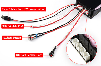
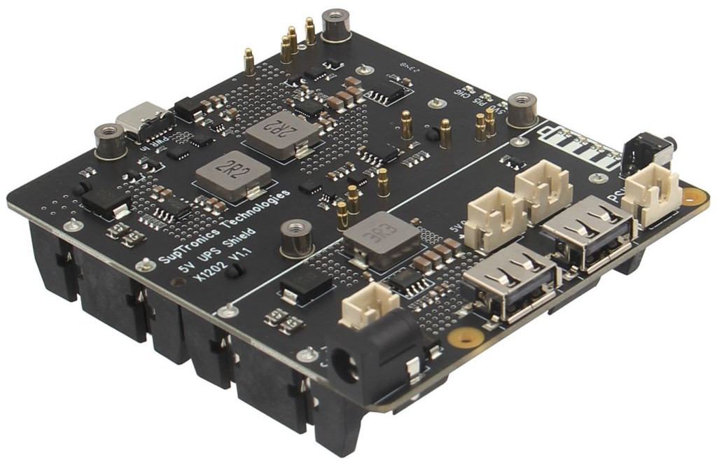
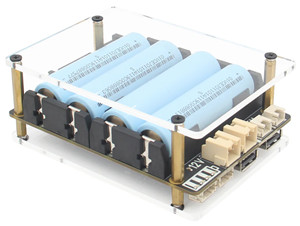
Geekworm X1202 UPS 5.1V/5A HAT for Pi 5
Geekworm X1202 4-Cell 18650 5.1V 5A UPS HAT for Raspberry Pi 5 Series
Vendor: Greekworm X1202
Resources:
Geekworm X-UPS1 12V/5V/3A Dual Output Universal SBC Stackable UPS Shield
Geekworm X-UPS1 12V/5V Dual Output Universal SBC Stackable UPS Shield
Vendor: Greekworm.com
Compatibility:
Compatible with most Single-Board computers (SBC) that use 12V DC or 5V DC, including Orange Pi 5, Jetson Nano, Raspberry Pi, Tinker Board, Arduino, and others.
Specifications:
- Power input (single board): 6 to 24V DC ±5%, ≥3 A
- Output voltages: 12V DC at 3A ± 5%, 5.1V DC at 3A ±5%
- Stackability: Boards can be stacked to increase output current and extend battery life
- Total output Current: 3A multiplied by the number of stacked boards
- Charging Configuration: Multiple power adapters can be used simultaneously when boards are stacked
Stack Boards:
- You can use a single board to turn all stacked boards On and Off. Note that the board used to turn them On must also be used to turn them Off.
- Only one AL_ON jumper cap should be shorted to enable the Always Power On function when stacking multiple X-UPS1 shields.
- To disable the 12V output when stacking multiple X-UPS1 shields, ensure that all 12 OFF jumper caps are shorted.
Resources:
- X-UPS Manual (WiKi)
- PCB Dimension: X-UPS1_Dimension
1.4 HAT Boards for Pi 5
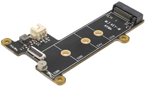
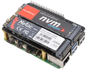
Geekworm X1001 PCIe to M.2 Key-M NVMe Adapter
Geekworm X1004 PCIe to Dual 2280 NVMe Shield for Pi 5
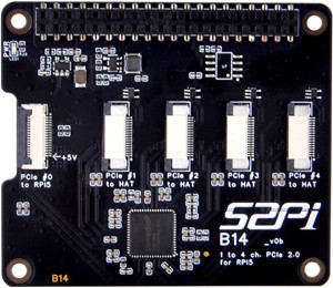
GeeekPi Dual FPC PCIe HAT
GeeekPi Dual FPC PCIe HAT B12 HAT 1 to 2 PCIe Interface with 40Pin GPIO Pin Header
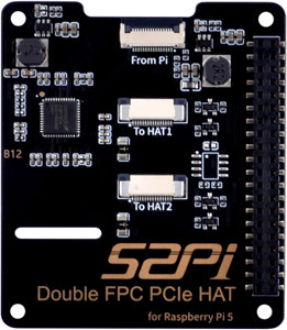
Vendor: Amazon.com
Resources:
GeeekPi Quad FPC PCIe HAT
Coral M.2 Accelerator with Dual Edge TPU (8 TOPS)
The Coral M.2 Accelerator with Dual Edge TPU is a compact AI accelerator module that delivers high-performance machine learning inference at the edge. Featuring two Edge TPU cores, it significantly boosts the processing power available for tasks like image classification, object detection, and other deep learning applications while operating with low latency and power consumption.
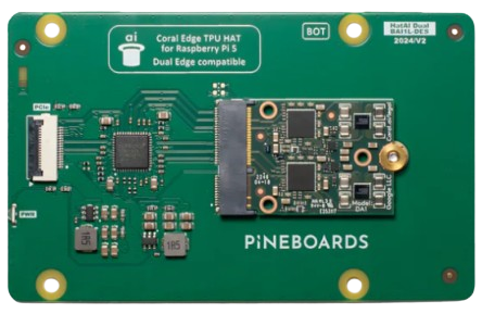
Key Features:
- Dual Edge TPU Cores: With two dedicated Edge TPU chips onboard, the accelerator can handle more complex models or run multiple models concurrently, offering improved throughput compared to single-TPU solutions.
- High-Speed Inference: Optimized for TensorFlow Lite models, it is ideal for applications requiring real-time processing, such as robotics, smart cameras, and various IoT devices.
- Compact M.2 Form Factor: Its small M.2 design makes it especially suited for integration into embedded systems without consuming much space.
Vendor: Coral.ai
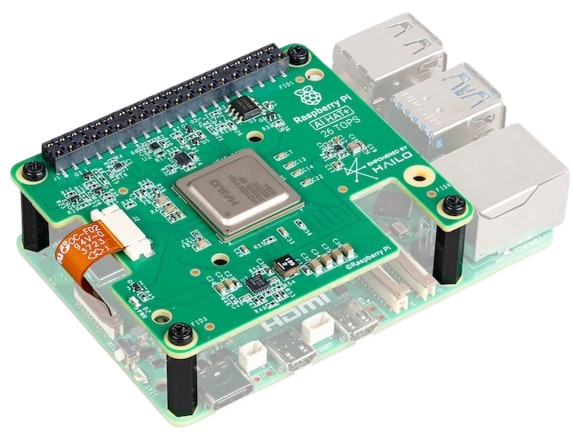
Raspberry Pi AI HAT+ (Hailo-8/8L 13/26 TOPS)
The Raspberry Pi AI HAT+ is an advanced add-on board that brings cutting-edge artificial intelligence capabilities to your Raspberry Pi projects. It features a built-in Hailo AI accelerator, enabling efficient neural network inference for various applications such as computer vision, robotics, process control, security, and home automation. Designed for compatibility with Raspberry Pi 5, the AI HAT+ offers two performance variants: one delivering 13 TOPS using the Hailo-8L accelerator—ideal for moderate workloads with performance similar to the AI Kit—and another delivering 26 TOPS with the Hailo-8 accelerator, which can handle larger networks, run models faster, and simultaneously manage multiple networks.
Communicating through Raspberry Pi 5’s PCIe interface, the board is automatically recognized by the host system. This seamless integration allows Raspberry Pi OS to utilize the onboard NPU for supported AI tasks—such as with the rpicam-apps camera applications that leverage the NPU for efficient post-processing. Along with its robust software stack, the AI HAT+ simplifies the deployment of AI models, making advanced machine-learning techniques accessible to seasoned developers and hobbyists.
Resources:
1.5 Screen for Pi
DeskPi 7.84 inch Touch Screen 1280x400 TFT LCD Screen

This 7.84-inch LCD screen is designed for a 10-inch server 2U rack (Rackmate T0/T1/T2 series). It has a high-definition display, stable performance, and easy installation. It is suitable for server monitoring and maintenance data management.
Specifications:
- Screen size: 7.84 inch
- Resolution: 1280 x 400, 350cd/m², 60Hz refresh rate
- Display type: TFT LCD
- Touch: with touch
- Interface type: HDMI
- Power supply: DC 5V
Configuration:
Raspberry Pi 4 + DeskPi 7.84 inch (1280×400) Setup Guide
Configure the Pi 4 to drive a 7.84″ HDMI + touch display at 1280×400 using FKMS and custom hdmi_timings, with optional rotation and touch alignment.
- Backup and open the config file
sudo cp /boot/firmware/config.txt /boot/firmware/config.backup sudo nano /boot/firmware/config.txt - Disable KMS and enable FKMS, and add the custom mode
Paste this block near the end of the file. Remove any non-comment text lines.
# Disable KMS, and enable FKMS dtoverlay=vc4-fkms-v3d #dtoverlay=vc4-kms-v3d max_framebuffers=2 # --- DeskPi / WisdPi 7.84" 1280x400 fixed output --- display_auto_detect=0 # Use HDMI + custom mode hdmi_force_hotplug=1 hdmi_group=2 hdmi_mode=87 hdmi_ignore_edid=0xa5000080 # Optional: force preferred mode hdmi_drive=2 # Custom 1280x400@60 timing (width first, height later) hdmi_timings=1280 0 100 10 140 400 10 20 20 2 0 0 0 60 0 43000000 3 # Disable compensation for displays with overscan disable_overscan=1 framebuffer_width=1280 framebuffer_height=400 # Rotation: 1=90°, 2=180°, 3=270° #display_rotate=3 gpu_mem=64 - Save and reboot
# In nano: Ctrl+O → Enter → Ctrl+X sudo reboot - Verify mode (FKMS path)
kmsprint | grep -A3 HDMI Connector 0 (90) HDMI-A-1 (connected) Encoder 0 (89) TMDS Crtc 0 (88) 43.000 1280/100/10/140/+ 400/20/20/2/+ 64 (63.59) Plane 0 (32) fb-id: 98 (crtcs: 0) 0,0 1280x400 -> 0,0 1280x400 (XR24 AR24 XB24 AB24 RX24 BX24 RG16 RG24 BG24 YU16 YU12 YV12 NV12 NV21 P030)
Should show .

Purchase Link:
- US Amazon: https://www.amazon.com/dp/B0F3C5R2BZ
