Tiva Lab 01: Blinking LEDs
This lab introduces the fundamentals of embedded programming using the TI Tiva LaunchPad series. Participants gain practical experience with the Keil μVision IDE, GPIO configurations, and bit-wise operations by developing simple firmware to blink onboard LEDs. The lab reinforces the importance of infinite loops in microcontroller applications and lays the groundwork for more complex embedded projects.
Introduction
Embedded systems rely on simple components like LEDs to provide immediate visual feedback and facilitate debugging. This lab uses the TI Tiva LaunchPad boards (EK-TM4C123GXL and EK-TM4C1294XL) to demonstrate core embedded programming concepts. Participants will explore the Keil μVision IDE, practice setting up projects in C, and learn how to manipulate GPIO pins using #define statements and bit-wise operations. The lab underscores the importance of continuous loops (e.g., while(1)) in embedded applications, which run independently of an operating system.
Objective
- Project Setup with Keil IDE: Familiarize with the Keil IDE by creating a new C project tailored for the TI Tiva LaunchPad Boards.
- Code Optimization with #define: Utilize #define statements to make the code more understandable and efficient.
- GPIO Configuration Mastery: Learn to set up and control GPIO for output operations, specifically for LED control.
- Bit-wise Operations: Grasp the usage of bit-wise operators to manipulate specific GPIO pins, turning LEDs on or off.
- LED Feedback Control: Reprogram the Tiva board to alter the blinking behavior of its onboard LEDs.
- Understanding Infinite Loops: Comprehend the significance of the "while(1)" loop in embedded systems and its necessity for continuous operation.
Required Reading Materials
- Lesson 07: Create an ARM C Application with Keil μVision MDK-ARM
- Lesson 09: GPIO Ports and Configurations
- Set, Clear, Toggle, and Check Bit Value in C
- Polling Method in Embedded Programming
Components Required
| Component/Device | Description | Quantity |
|---|---|---|
| TM4C1294 onboard Green LEDs (LED1 ~ LED4) | × 4 | |
| TM4C123G onboard RGB LED | × 1 |
Background
The Tiva launchPad has rows of connectors along both sides that connect to several electronic devices and plug-in 'shields' that extend its capability. The EK-TM4C123GXL LaunchPad has a single RGB LED on the board, and the EK-TM4C1294XL LaunchPad has four LEDs. Those can be used on your embedded applications. The onboard LEDs may blink when you first connect the board to a USB plug. That is because the boards are generally shipped with the Blink sketch pre-installed.
In this lab, we will reprogram the Tiva board with our Blink code and then change the rate at which it blinks.
Please follow Lesson 07: Create an ARM C Application with Keil μVision MDK-ARM to learn how to set up the Keil μVision IDE, create a new project, download and debug the code.
Circuit Diagram
The onboard switches and LEDs for Tiva LaunchPads are as shown below:
EK-TM4C123GXL LaunchPad - Circuit
The EK-TM4C123GXL LaunchPad comes with an RGB LED and two user buttons. Table 1 shows how these features are connected to the pins on the microcontroller.
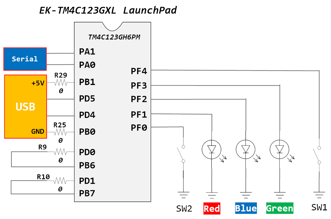
Table 1: User Switches and RGB LED Signals
| GPIO Pin | Pin Function | User Device |
| PF4 | GPIO | SW1 |
| PF0 | GPIO | SW2 |
| PF1 | GPIO | RGB LED (Red) |
| PF2 | GPIO | RGB LED (Blue) |
| PF3 | GPIO | RGB LED (Green) |
Table2: Pin Configurations for TM4C123G
| Device | Port.Pin | Signal Type | PCTL | Direction | Drive Mode |
|---|---|---|---|---|---|
In your code, you must configure GPIO Port F pin 1 and pin 3 as outputs.
EK-TM4C1294XL LaunchPad - Circuit
The EK-TM4C1294XL LaunchPad comes with four green LEDs and two user buttons. Table 2 shows how these features are connected to the pins on the microcontroller.
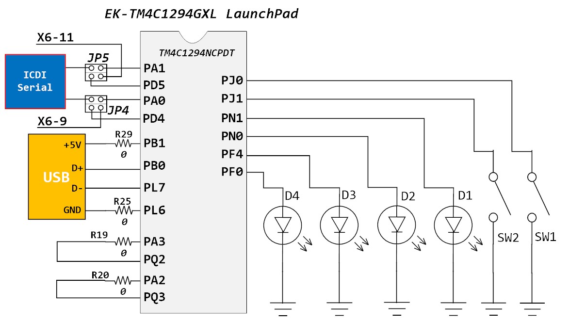
Table 3: User Switches and Green LED Signals
| GPIO Pin | Pin Function | User Device |
| PJ0 | GPIO | SW1 |
| PJ1 | GPIO | SW2 |
| PN1 | GPIO | LED1 |
| PN0 | GPIO | LED2 |
| PF4 | GPIO | LED3 |
| PF0 | GPIO | LED4 |
Table 4: Pin Configurations for TM4C1294
| Device | Port.Pin | Signal Type | PCTL | Direction | Drive Mode |
|---|---|---|---|---|---|
In your code, you need to initialize GPIO Port N pin 0 and pin 1 as outputs.
Procedure
In this lab, you will learn how to create a C project for the Tiva LaunchPad board and configure the GPIO ports to blink the onboard LED.
* Before doing this lab, you must first study "Lesson 07: Create an ARM C Application with Keil μVision MDK-ARM".
- Please create a new folder under the EE3450 folder and name it Lab01_BlinkingLEDs_1. Then, double-click the folder you just created to jump into it.
- Launch the Keil μVisio, create a new project, and save the project as Lab01_BlinkingLEDs_1.
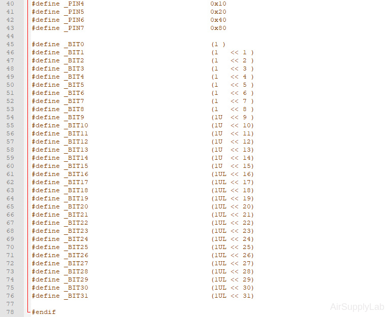
- Create predefined symbolic constants for the GPIO configurations.
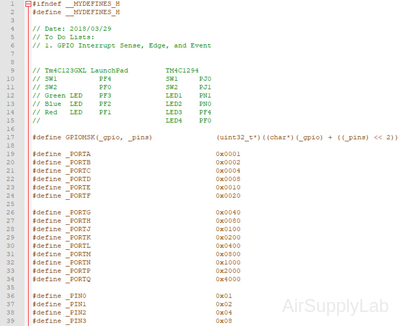
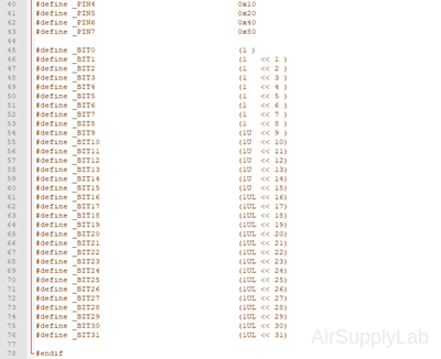
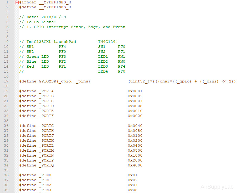
Create MyDefines.h
Create MyDefines.h
Create the MyDefines.h file and add it to your project.
- Use Notepad++ or other text editors to add the following definitions to the file, then save the file inside the Common folder and name it "MyDefines.h"
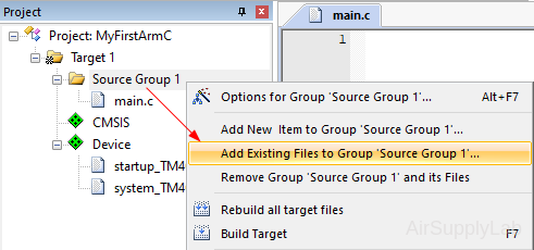
- Go back to the Keil main window. Right-click on Source Group 1 and click Add Existing Files to Group 'Source Group 1'...
- In the open window, change the location to the Common folder, then change the file type to the Text file (*.txt; *.h; *.inc). Select MyDefines.h file, or enter the File name "MyDefines".
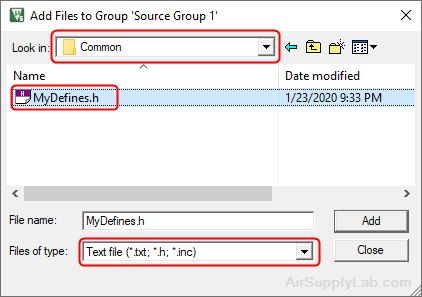
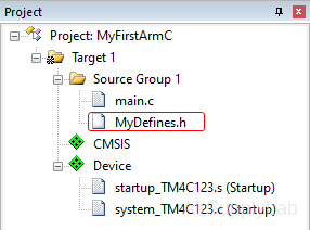
Click Add, and then click Close to close the window. - Now you have already added MyDefines.h file to your project.
- Add the Common folder to the Include Paths. So the compiler will know where to find the MyDefines.h file.
Open the Option for Target window, change the tab to C/C++, and add the Common folder on the Include Paths field.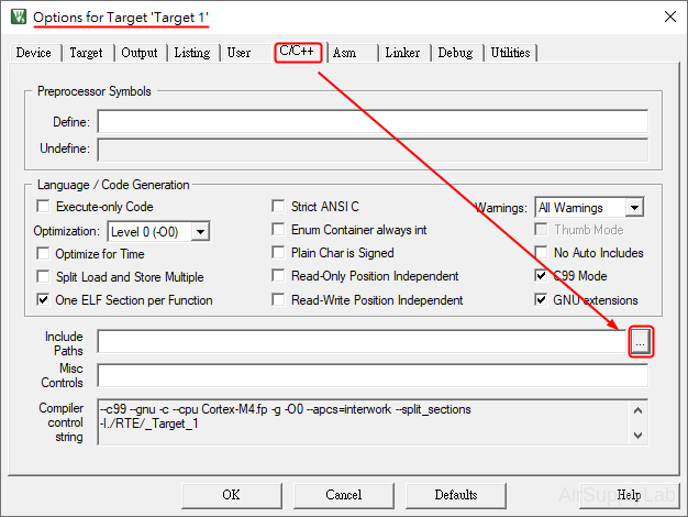
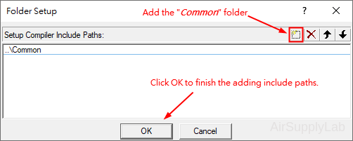
Click OK to close the Options window.
- Use Notepad++ or other text editors to add the following definitions to the file, then save the file inside the Common folder and name it "MyDefines.h"
- Copy-paste the following code to your main.c file.
Lab Template Firmware Source Code
This section provides the template firmware source code for the TM4C123G and TM4C1294 platforms used in these laboratory exercises. Explanatory notes are included to help readers understand the purpose and operation of each major part of the program.
The provided code is intended as a reference starting point and may be copied into the project as needed. Since the template is not a final, complete program, it should be reviewed and modified to meet the requirements of each experiment. Unnecessary statements may be commented out, and appropriate comments should be added to clearly document the program structure and implementation details.
EK-TM4C123GXL LaunchPad - main.c
#include <stdio.h>
#include <stdlib.h>
#include <stdint.h>
#include <stdbool.h>

#include "TM4C123GH6PM.h"
#include "MyDefines.h"

void DelayMs(int ms);   // Software Delay Function
void Setup_GPIO(void);

int main(void)
{
    // Place your initialization/startup code here (e.g. Setup_GPIO() )
    Setup_GPIO();

    while (1) {
        // Place your application code here

    }
}
//------------------------------------------------------------------------------
/*
Device      Port.Pins       DIR     DriveMode
LEDR
LEDG
SW1
SW2

Port ____
*/

void Setup_GPIO(void)
{
    // Configure GPIOs
    // 1. Enable Clock to the GPIO Modules (SYSCTL->RCGCGPIO |= (_PORTs);)
    SYSCTL->RCGCGPIO |= (__);
    // allow time for clock to stabilize (SYSCTL->PRGPIO & (_PORTs))
    while ((SYSCTL->PRGPIO & (__)) != (__)) {};
    // 2. Unlock GPIO only PD7, PF0 on TM4C123G; PD7, PE7 on TM4C1294 (GPIOx->LOCK = 0x4C4F434B; and GPIOx->CR = _PINs;)
    // Unlock PF0
    GPIOF->LOCK = 0x4C4F434B;   // Unlock for GPIOF
    GPIOF->CR |= _PIN0;         // Commit for PIN0
    // 3. Set Analog Mode Select bits for each Port (GPIOx->AMSEL = _PINs;)
    // 4. Set Port Control Register for each Port (GPIOx->PCTL = PMCn << _PTCL_PINn, check the PCTL table)
    // 5. Set Alternate Function Select bits for each Port (GPIOx->AFSEL = _PINs;)
    // 6. Set Output pins for each Port (Direction of the Pins: GPIOx->DIR = _PINs;)

    // 7. Set PUR bits (internal Pull-Up Resistor), PDR (Pull-Down Resistor), ODR (Open Drain) for each Port

    // 8. Set Digital ENable register on all port.pins (GPIOx->DEN = _PINs;)

}
//------------------------------------------------------------------------------
// Delay ms milliseconds (4167:50MHz TM4C123G CPU, 1605:16MHz TM4C123G CPU Clock)
void DelayMs(int ms)
{
    volatile int i, j;
    for (i = 0; i < ms; i++)
        for (j = 0; j < 4167; j++) {} // Do nothing for 1ms
}
EK-TM4C1294XL LaunchPad - main.c
#include <stdio.h> #include <stdlib.h> #include <stdint.h> #include <stdbool.h> #include "TM4C1294NCPDT.h" #include "MyDefines.h" void DelayMs(int ms); // Software Delay Function void Setup_GPIO(void); int main(void) { // Place your initialization/startup code here (e.g. Setup_GPIO() ) Setup_GPIO(); while (1) { // Place your application code here } } //------------------------------------------------------------------------------ /* Device Port.Pins DIR DriveMode LED1 LED2 SW1 SW2 Port ____ */ void Setup_GPIO(void) { // Configure GPIOs // 1. Enable Clock to the GPIO Modules (SYSCTL->RCGCGPIO |= (_PORTs);) SYSCTL->RCGCGPIO |= (__); // allow time for clock to stabilize (SYSCTL->PRGPIO & (_PORTs)) while ((SYSCTL->PRGPIO & (__)) != (__)) {}; // 2. Unlock GPIO only PD7, PF0 on TM4C123G; PD7, PE7 on TM4C1294 (GPIOx->LOCK = 0x4C4F434B; and GPIOx->CR = _PINs;)
// Unlock PD7
// GPIOD_AHB->LOCK = 0x4C4F434B;
// while (GPIOD_AHB->LOCK != 0);
// GPIOD_AHB->CR |= _PIN7; // 3. Set Analog Mode Select bits for each Port (GPIOx->AMSEL = _PINs;) // 4. Set Port Control Register for each Port (GPIOx->PCTL = PMCn << _PTCL_PINn, check the PCTL table) // 5. Set Alternate Function Select bits for each Port (GPIOx->AFSEL = _PINs;) // 6. Set Output pins for each Port (Direction of the Pins: GPIOx->DIR = _PINs;) // 7. Set PUR bits (internal Pull-Up Resistor), PDR (Pull-Down Resistor), ODR (Open Drain) for each Port // 8. Set Digital ENable register on all port.pins (GPIOx->DEN = _PINs;) } //------------------------------------------------------------------------------ // Delay ms milliseconds (1605: 16MHz TM4C1294 CPU Clock) void DelayMs(int ms) { volatile int i, j; for (i = 0; i < ms; i++) for (j = 0; j < 1605; j++) {} // // Do nothing for 1ms } - Modify the Setup_GPIO() function based on the Pin Configuration Table (table 2 or 4) to configure the onboard switches and LEDs.
GPIO Initialization and Configuration
GPIO Initialization Configuration
Next, we need to configure all the GPIO ports and pins that are used in the design.
According to the pin connections, complete the following GPIO configurations for each port. Fills the pin field by the value below:
- 0: Clean the bit
- 1: Set the bit
- x: Do not change the bit
- d: Do not care
For both TM4C123GXL and TM4C1294XL LaunchPads, the Port C [3:0] are used for JTAG/SWD. Therefore, when you configure Port C, you have to use bitwise operators to make sure your new configuration settings do not affect the JTAG/SWD function (PC3 ~ PC0).
Most of GPIO pins are configured as GPIOs and tri-stated by default (GPIOPCTL = 0, CPIOAFSEL = 0, GPIODIR = 0, GPIOPUR = 0, GPIOPDR = 0, GPIOODR = 0)
- Enable Clock to the GPIO Modules (RCGCGPIO register)
TM4C123G: SYSCTL->RCGCGPIO |= (_PORTs); |= binary = hex
8 4 2 1 8 4 2 1 7 6 5 4 3 2 1 0 bit Port F Port E Port D Port C Port B Port A port 0 0 -
TM4C1294: SYSCTL->RCGCGPIO |= (_PORTs); |= binary = hex
After enabling the clock signal, check the PRGPIO register until the corresponding bit is set to 1.8 4 2 1 8 4 2 1 8 4 2 1 8 4 2 1 15 14 13 12 11 10 9 8 7 6 5 4 3 2 1 0 bit Port Q Port P Port N Port M Port L Port K Port J Port H Port G Port F Port E Port D Port C Port B Port A port 0 - - -
In Assembly:
            LDR     R0, =SYSCTL_PRGPIO_R
Wait4GPIO   LDR     R1, [R0]
            TST     R1, #(__)
            BEQ     Wait4GPIO
In c:
while ( (SYSCTL->PRGPIO & ____ ) != ____ ) {}; - Unlock Port
TM4C123G: PD7 and PF0 are locked after reset.
TM4C1294: PD7 and PE7 are locked after reset
If those pins are used in the design, they must be unlocked first. To unlock the port, 0x4C4F434B must be written into the GPIOLOCK register and uncommit it by setting the GPIOCR register.
8 4 2 1 8 4 2 1 7 6 5 4 3 2 1 0 bit Port Pin 7 Pin 6 Pin 5 Pin 4 - Pin 3 Pin 2 Pin 1 Pin 0 pin Value in Hex Register Value to Register - - = ➤ GPIO ->LOCK = 0x4C4F434B - - = ➤ GPIO ->CR - - = ➤ GPIO ->LOCK = 0x4C4F434B - - = ➤ GPIO ->CR
Convert above configuration into registers
- GPIO Analog Mode Select
If any pin is used as an Analog signal (check Signal Type field on table 1), the appropriate bit in AMSEL must be set.
- 0: Digital signal
- 1: Analog signal
8 4 2 1 8 4 2 1 7 6 5 4 3 2 1 0 bit Port Pin 7 Pin 6 Pin 5 Pin 4 - Pin 3 Pin 2 Pin 1 Pin 0 pin Value in Hex Register Value to Register - - = ➤ GPIO ->AMSEL - - = ➤ GPIO ->AMSEL - - = ➤ GPIO ->AMSEL - - = ➤ GPIO ->AMSEL - - = ➤ GPIO ->AMSEL - - = ➤ GPIO ->AMSEL - - = ➤ GPIO ->AMSEL - GPIO Port Control (PCTL)
The PCTL register is used to select the specific peripheral signal for each GPIO pin when using the alternate function mode.
- 0: GPIO
- 1~0xF: Check the GPIO Pins and Alternate Function table
8421 8421 8421 8421 8421 8421 8421 8421 31~28 27~24 23~20 19~16 15~12 11~8 7~4 3~0 bit Port Pin 7 Pin 6 Pin 5 Pin 4 - Pin 3 Pin 2 Pin 1 Pin 0 pin Value in Hex Register Value to Register - - = ➤ GPIO ->PCTL - - = ➤ GPIO ->PCTL - - = ➤ GPIO ->PCTL - - = ➤ GPIO ->PCTL - - = ➤ GPIO ->PCTL - - = ➤ GPIO ->PCTL - - = ➤ GPIO ->PCTL - GPIO Alternate Function Select (AFSEL)
Setting a bit in the AFSEL register configures the corresponding GPIO pin to be controlled by PCTL peripheral function.
- 0: General I/O
- 1: Pin connected to the digital function defined in the PCTL register
8 4 2 1 8 4 2 1 7 6 5 4 3 2 1 0 bit Port Pin 7 Pin 6 Pin 5 Pin 4 - Pin 3 Pin 2 Pin 1 Pin 0 pin Value in Hex Register Value to Register - - = ➤ GPIO ->AFSEL - - = ➤ GPIO ->AFSEL - - = ➤ GPIO ->AFSEL - - = ➤ GPIO ->AFSEL - - = ➤ GPIO ->AFSEL - - = ➤ GPIO ->AFSEL - - = ➤ GPIO ->AFSEL - GPIO Pin Direction (DIR)
Set pin direction
- 0: Input pin
- 1: Output pin
8 4 2 1 8 4 2 1 7 6 5 4 3 2 1 0 bit Port Pin 7 Pin 6 Pin 5 Pin 4 - Pin 3 Pin 2 Pin 1 Pin 0 pin Value in Hex Register Value to Register - - = ➤ GPIO ->DIR - - = ➤ GPIO ->DIR - - = ➤ GPIO ->DIR - - = ➤ GPIO ->DIR - - = ➤ GPIO ->DIR - - = ➤ GPIO ->DIR - - = ➤ GPIO ->DIR - Internal Pull-Up Resistor (PUR), Pull-Down Resistor (PDR), and Open-Drain (ODR)
PUR: The pull-up control register
PDR: The pull-down control register
ODR: The open-drain control register
- 0: Disable
- 1: Enable
8 4 2 1 8 4 2 1 7 6 5 4 3 2 1 0 bit Port Pin 7 Pin 6 Pin 5 Pin 4 - Pin 3 Pin 2 Pin 1 Pin 0 pin Value in Hex Register Value to Register - - = ➤ GPIO -> - - = ➤ GPIO -> - - = ➤ GPIO -> - - = ➤ GPIO -> - - = ➤ GPIO -> - - = ➤ GPIO -> - - = ➤ GPIO -> - GPIO Digital Enable
Enables all the pins that are used in the design, including GPIO pins and alternate function pins.
- 0: Pin undriven
- 1: Enable pin
8 4 2 1 8 4 2 1 7 6 5 4 3 2 1 0 bit Port Pin 7 Pin 6 Pin 5 Pin 4 - Pin 3 Pin 2 Pin 1 Pin 0 pin Value in Hex Register Value to Register - - = ➤ GPIO ->DEN - - = ➤ GPIO ->DEN - - = ➤ GPIO ->DEN - - = ➤ GPIO ->DEN - - = ➤ GPIO ->DEN - - = ➤ GPIO ->DEN - - = ➤ GPIO ->DEN
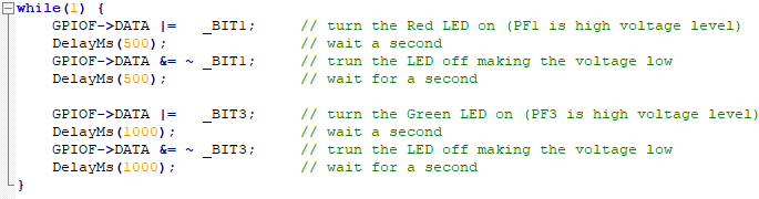
- Inside the while(1) loop, the commands first of all turn the LED pin on (high), then delay for 1000 milliseconds (1 second), then turn the LED pin off and pause for another second.
EK-TM4C123GXL LaunchPad - while loop
Blinking the Red LED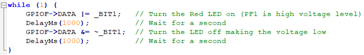
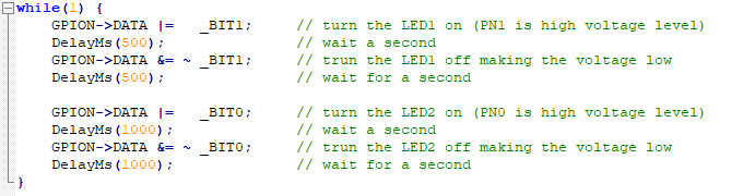
EK-TM4C1294XL LaunchPad - while loop
Blinking the LED1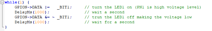
Every C code must have a main() function, which is the entry point for the system. In the main() function, the line while(1) is the most popular used in an application for embedded microcontrollers. The line while(1) creates an infinite loop that never stops executing. It executes over and over and over again unless the program is intentionally stopped or there is some condition under this loop that gets met that takes out of this infinite loop.
Why do embedded programs contain an infinite loop? While personal computers have an operating system, embedded microcontrollers generally do not. Once a program has been executed on a personal computer, it returns control to the computer's operating system when the program is finished. An embedded microcontroller, however, does not have an operating system and cannot be allowed to fall out of the program at any time. Hence, every embedded microcontroller application has an infinite loop built into it somewhere, such as the line while(1). This prevents the program from running out of things to do and doing random things that may be undesirable.
Lab Experiments
Exp #1.1: Blinking Red and Green LEDs
Now, add codes to blink the green LED (LED2) every second after blinking the red LED (LED1).
Build the code. If there are no errors, download the object code to the Tiva board. You should see the LED start to blink as below.

Blinking LEDs on TM4C123G Board
Blinking LEDs on TM4C1294 Board
Exp #1.2: Two LEDs Blink Simultaneously but in Different Intervals
Control two LEDs so they operate concurrently (i.e., without waiting on each other) while blinking at different intervals:
- RED (LED1): toggle every 500 ms
- GREEN (LED2): toggle every 1000 ms
This lab emphasizes a non-blocking polling design using a common time base and per-LED countdown variables.
Now, create a second project:
- Create a project folder named "Lab01_BlinkingLEDs_2" under the EE3450 folder.
- Follow the previous procedures to create a second project.
- You can copy the main.c file from the previous project.
In this experiment, the system still controls two LEDs: Both are lit up simultaneously, but each LED will blink at different intervals. The Red LED (LED1) blinks every 500 ms, and the Green LED (LED2) blinks at 1000 ms.
You might think that you need to duplicate the same code and then modify that code to control the second LED, such as the following:
EK-TM4C123GXL LaunchPad - two LEDs
EK-TM4C1294XL LaunchPad - two LEDs
However, you will see that the Red LED (or LED1) will be lit up for 500 ms and then turned off for 500 ms. Afterward, the Green LED (or LED2) will turn on for 1000 ms and off for 1000 ms. It will repeat the same action.
The two LEDs will interact; when one is active, the other is inactive. However, they do not act at the same time. This is an incorrect function design.
Read Polling Method in Embedded Programming - Same Polling Cycles, Different Delay session. Using the following pseudoscience to design the function:
Set timeLoop1, and timeLoop2 to 0
loop
if timeLoop1 is zero
toggle Red LED or LED1
set timeLoop1 value to the number of loops for 500 ms delay cycles
if timeLoop2 is zero
toggle Green LED or LED2
set timeLoop2 value to the number of loops for 1000 ms delay cycles
delay for 10 ms (each loop has 10 ms delay)
if timeLoop1 is greater than zero
decrease timeLoop1 by 1
if timeLoop2 greater than zero
decrease timeLoop2 by 1
endloop
You must create two variables in the code to store the different timer delays. To simplify the coding, we will ignore the execution time of all instructions and add a 10ms delay in the loop. If you need to delay the timer by 30ms, you must set the value of the timer to 3 to get three delay cycles (each delay cycle is 10ms).
The final results are shown below:

Blinking LEDs on TM4C123G Board

Blinking LEDs on TM4C1294 Board
Questions
Read the following datasheet for the EK-TM4C123GXL or EK-TM4C1294XL board, then find the answer to the questions.
- The CPU used on the Tiva board is an ARM Cortex-M4-based processor. What is the maximum operating frequency of the processor on EK-TM4C123GXL and EK-TM4C1294XL boards?
- List all external clock sources on your Tiva LaunchPad board.
- The onboard In-Circuit Debug Interface (ICDI) supports a UART communication port connected to the Tiva LaunchPad. Which GPIO pins on the Tiva LaunchPad are used for UART communication?
- Each Tiva Launchpad has two microcontrollers. What is the purpose?