Tiva Lab 008: PWM RC Servo Controller
Overview
- Learn how to configure a PWM signal to control the RC servo
- Learn how to calculate the LOAD value and the range of CMP value
Required Reading Material
- Pulse-Width Modulation (PWM)
- Lesson 13: Pulse-Width Modulation (PWM)
- Servo Specifications and Reviews:
Overview
RC Servo
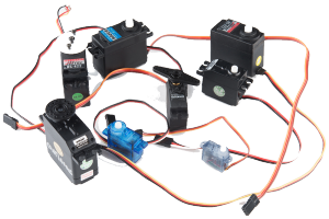
RC Servo is a type of gear motor that is designed with limited rotation angles like 60°, 90°, 180°, and so on. It is great for beginners who want to make stuff move without building a motor controller with feedback and a gearbox. Originally used in remote-controlled cars and airplanes. It is controlled by sending a PWM signal from the microcontroller. The PWM signal tells the servo what position it should move to.
- The servo can be positioned from 0 to 180 degree
- An internal DC motor connected to a potentiometer
- High torque gearing
- Internal feedback circuitry to control motor position
Connector and Wire Colors
Most standard RC servos use a standard type of 3-pin plug. The connector is a female, 3-pin, 0.1" (2.54 mm) pitch header. The wiring color used on the servo is not always consistent, there are several color codes at play. But the pins are usually in the same order, just the colors are different.
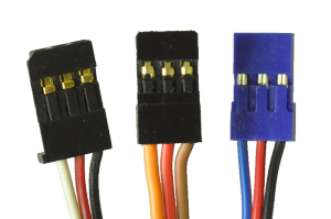
- Red wire — Servo power (Vservo, battery positive terminal)
- Brown or Black wire — Ground (GND, battery negative terminal)
- Orange, Yellow, white, or blue wire — Servo control signal line (PWM signal)
Please check the datasheet or specs for your servo to determine the proper power supply voltage, and please take care to plug the servo into your device in the proper orientation. Plugging it in backward could break the servo.
Control Signal
The third pin of the servo connector carries the control signal, used to tell the motor where to go. This control signal is a PWM signal. The frequency of PWM is in a range of 40 Hz to 200 Hz. Typically, the servo uses a 50 Hz (20 ms period) PWM signal. The servo position is not defined by the PWM duty cycle, but only by the pulse width. Since the position of the servo is determined by the width of the "on" pulse. The off-time can be from 5 ms to 40 ms, without any impact on the position. Different servos may have different minimal and maximal pulse widths. Usually, the pulse width is in the range of 1 ms to 2 ms. The servo will rotate in the clockwise or counter-clockwise direction. The direction of rotation of the digital servos can be changed by a specific programmer device. The neutral is defined to be the center of rotation. It is important to note that different servos will have different constraints on their rotation, but they all have a neutral position and that position is always a pulse width of 1.5 ms.
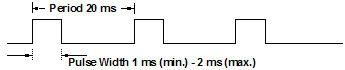 Figure 1: Typical PWM Signal for the Most of RC Servos
When the power is turned off, the servo's rotor stays in its position. This means that, when power is turned on again, the controller may not know the rotor's angle. For this reason, it's common to return the servo to the neutral position as soon as power becomes available.
Due to the fact that the servo is appropriate for hobbyists, a detailed datasheet may not available. However, the limiting values for signal width can be determined by the experiment.
Deadband width: Minimum pulse width (in microseconds) that the servo will respond to. determines the minimum move that can specify, 10 μs would be around 1.8º; 1 μs would be 0.18º.
Tower Pro SG90 9G Micro Servo
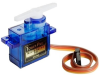
RC Servo is a type of geared motor that can rotate 90 or 180 degrees. It is great for beginners who want to make stuff move without building a motor controller with feedback and a gearbox. Originally used in remote-controlled cars and airplanes. It is controlled by sending a PWM signal from the microcontroller. The PWM signal tells the servo what position it should move to.
Connection
Most standard RC servos use a standard type of 3-pin plus. The connector is a female, 3-pin, 0.1" (2.54 mm) pitch header. The wiring color used on the servo is not always consistent. There are several color codes at play. But the pins are usually in the same order, and just the colors are different.
- Orange, Yellow, white, or blue wire — Servo control signal line (PWM signal)
- Red wire — Servo power (Vservo, battery positive terminal)
- Brown or Black wire — Ground (GND, battery negative terminal)
SG90 servo can rotate approximately 180 degrees (90 in each direction).
Wired Connection

Position "0" degree ( 0.5 ms Pulse) is all the way to the left, "90" degree (1.5ms pulse) in the middle, "180" degree (2.4ms pulse) is all the way to the right.
Calculations
The frequency of the PWM signal for RC Servo is 50 Hz, and the PWM type is left-aligned PWM.
\({f_{PWM,Servo}} = 50Hz\)
Check the datasheet, and find out the range of PWM pulse widths for the RC Servo that is used in the lab:
PulseWidth0°(Left-Position) = _______ ms; PulseWidth180°(Right-Position) = _______ ms
In the first step, you have to know what is the system clock frequency. The default system clock frequency is:
- EK-TM4C123GXL LaunchPad: By default, the Keil C startup.s will change the system frequency to 50 MHz. You need to disable the Clock Configuration to change the clock to 16 MHz. Otherwise, you have to use 50 MHz as the system clock in the calculation when you calculate the frequency for the PWM Timer.
- EK-TM4C1294XL LaunchPad: The system clock is 16 MHz.
The clock frequency for PWM Timer is the system clock divided by the PWM divisor, which is defined in the SYSCTL_RCC register (for TMC123G) or PWM_CC register (for TM4C1294).
\({f_{PWMTimer}} = \frac{{SysClk}}{{PWMDivsor}}\)
Calculate the count value for the PWM signal. This value will be set to the LOAD register, which is 16-bit length only. If the count value you calculated is over 65535 (= 216-1), you need to reduce the frequency of the PWM Timer by increasing the value of the PWM Divisor and then recalculating the count value again. The frequency of the PWM output signal for RC Servo is 50 Hz (the period time is 20 ms), therefore the count value for the PWM Timer counting for 20 ms is the period value that is saved in the LOAD register.
\(LOAD = Coun{t_{PWM,50Hz}} = \frac{{20ms}}{{{T_{PWMTimer}}}} = \frac{{{f_{PWMTimer}}}}{{50Hz}} \le 65535\)
Then, you need to calculate the CMP values for 0º (left-position) and 180º (right-position).
\(Dut{y_{0^\circ }} = \frac{{PulseWidt{h_{0^\circ }}}}{{20ms}}\)
\(CM{P_{0^\circ }} = LOAD \times (1 - Dut{y_{0^\circ }})\)
\(Dut{y_{180^\circ }} = \frac{{PulseWidt{h_{180^\circ }}}}{{20ms}}\)
\(CM{P_{180^\circ }} = LOAD \times (1 - Dut{y_{180^\circ }})\)
\(CM{P_{0^\circ }} \ge CMP \ge CM{P_{180^\circ }}\)
In your code, the value which is written into the CMP register can not exceed the range between CMP0 and CMP180, otherwise, the servo may be damaged, or can not work.
Required Components List
- Ti Tiva LaunchPad Board: TM4C123GXL or TM4C1294XL
- Servo motor: Tower Pro micro servo SG90 or other compatible servo motors
- Breadboard, Power adapter, and voltage regulator
- F-F, M-F, M-M wires
Circuit / Schematic Diagram
You need to define a GPIO pin from the Tiva launchPad as the PWM output and connect it with the RC Servo control pin. The power connected with the Servo must be provided from the breadboard power module. Do not connect the power source from the Tiva board.
Procedure
- Create a new folder under the EE3450 folder and name it Lab08_PWMServo.
- Launch the Keil μVisio and create a new project. Save the project to the project folder you just created in the previous step and set the project name to Lab08_PWMServo.
- Add the Common and ezTivaLIB folder to the include paths which is under the "Options for Target" setting.
- Add ezTiva LIB (ez123GLIB.lib or ez1294LIB.lib) into your project, and increase the stack and heap size under the "startup_TM4cXXX.s (Startup)" setting.
Configurations
| Device | Port.Pin | Signal Type | PCTL | Direction | Drive Mode |
|---|---|---|---|---|---|
PWM Connection and Configuration
PWM Initialization & Configuration
Find the frequency of the system clock, and calculate the frequency of the PWM Timer.
| System Clock SysClk (Hz) |
PWMDIV | fPWMTimer = SysClk / PWMDIV (Hz) |
Check the PCTL table (for 123G or 1294) to find the pins which support PWM peripheral signal
| GPIO Port.Pin |
PWM Module |
PCTL | PWM | |||||||
| Module (m) |
Generator (n) |
Signal GEN | Output | Signal Type | Output Frequency fPWM |
LOAD Value (16-bit) |
Initial CMP Value (16-bit) |
|||
You have to know the frequency of the System Clock (1), the frequency of PWM output signal (2), and the initial value for duty cycle (3). Then, calculate the LOAD value and CMP value.
\(LOA{D_{16bit}} = \frac{{{f_{PWMTimer}}}}{{{f_{PWM}}}}\)
For Left-Aligned PWM Signals
Calculate CMP value by duty cycle (%):
\(CM{P_{16bit}} = LOAD \times (1 - Dut{y_\% }) = \frac{{{f_{PWMTimer}}}}{{{f_{PWM}}}} \times (1 - Dut{y_\% })\)
Calculate CMP value by pulse width:
\(CM{P_{16bit}} = LOAD - \frac{{{T_{PulseWidth}}}}{{{T_{PWMTimer}}}} = ({T_{PWM}} - {T_{PulseWidth}}) \times {f_{PWMTimer}}\)
For Right-Aligned PWM Signals
Calculate CMP value by duty cycle (%):
\(CM{P_{16bit}} = LOAD \times Dut{y_\% } = \frac{{{f_{PWMTimer}}}}{{{f_{PWM}}}} \times Dut{y_\% }\)
Calculate CMP value by pulse width:
\(CM{P_{16bit}} = \frac{{{T_{PulseWidth}}}}{{{T_{PWMTimer}}}} = {T_{PulseWidth}} \times {f_{PWMTimer}}\)
The following steps show how to initialize PWM peripheral.
- Enable Clock to the PWM Modules (RCGCPWM register)
TM4C123G:
SYSCTL->RCGCPWM = MyDefines.h8 4 2 1 8 4 2 1 7 6 5 4 3 2 1 0 bit PWM
Module 1PWM
Module 0PWM 0 0 0 0 - 0 0
= binary = hex
TM4C1294:
SYSCTL->RCGCPWM = MyDefines.h8 4 2 1 8 4 2 1 7 6 5 4 3 2 1 0 bit PWM
Module 0PWM 0 0 0 0 - 0 0 0
= binary = hex
After enable clock signal, check the PRPWM register until the corresponding bit set to 1.
In C:
while ( (SYSCTL->PRPWM & (__) ) != (____ )) {}; - Enable and Setup Clock Divider for all PWM modules
USEPWMDIV: Enable PWM Clock Divisor
- 0: The system clock is the source for the PWM clock
- 1: The PWM clock divider is the source for the PWM clock
PWMDIV: PWM Unit Cloxk Divisor
- 0x0: /2
- 0x1: /4
- 0x2: /8
- 0x3: /16
- 0x4: /32
- 0x5: /64
TM4C123G:
SYSCTL->RCC &= ~(0x7 << 17); // RCC[19:17]=000 PWMDIVRCC 31 ~ 21 20 19 ~ 17 16 ~ 0 bit USEPWMDIV PWMDIV x x
SYSCTL->RCC |=
|= |=
TM4C1294:
PWM0->CC &= ~(0x7); // PWMCC[2:0]=000 PWMDIVPWMCC 31 ~ 9 8 7 ~ 3 2 ~ 0 bit USEPWMDIV PWMDIV x x
PWM0->CC |=
|= |= - PWM Signal Generation Control Register (PWMnCTL)
MODE: Counter Mode
- 0: Count-Down mode
- 1: Count-Up/Down mode
ENABLE: PWM Block Enable
- 0: The entire PWM generation block is disable and not not clocked
- 1: The PWM generation block is enabled and produces PWM signals
PWMnCTL 31 ~ 19 18 17 16 15 ~ 14 13 ~ 12 11 ~ 10 9 ~ 8 bit LATCH MINFLTPER FLTSRC DBFALLUPD DBRISEUPD DBCTLUPD GENBUPD x PWMnCTL 7 ~ 6 5 4 3 2 1 0 bit GENAUPD CMPBUPD CMPAUPD LOADUPD DEBUG MODE ENABLE PWM ->_ _CTL =
= = - Setup the Period of the PWM Signal (PWMnLOAD)
The 16-bit LOAD value is used to control the PWM period.
PWMnLOAD 31 ~ 16 15 ~ 0 bit LOAD PWM ->_ _LOAD =
- Setup the Initial Duty Cycle (PWMnCMPA / PWMnCMPB)
The PWMnCMPA / PWMnCMPB registers are used to compare against the PWM counter. When this value matches the counter, a pulse is output which can be configured to drive the pwmA and pwmB signals (via the PWMnGENA and PWMnGENB).
PWMnCMPA 31 ~ 16 15 ~ 0 bit CMPA PWM ->_ _CMPA =
PWMnCMPB 31 ~ 16 15 ~ 0 bit CMPB PWM ->_ _CMPB =
- Setup PWM Signal Type (PWMnGENA / PWMnGENB)
These register control the generation of the pwmA/pwmB signal based on the load and zero output pulses from the counter, as well as the compare A (CMPA) and compare B (CMPB) pulses from the comparators.
- 0x0: Do nothing
- 0x1: Invert PWM signal
- 0x2: Drive PWM signal Low
- 0x3: Drive PWM signal High
ACTCMPBD: Action for Comparator B in count-down mode
ACTCMPBU: Action for Comparator B in count-up mode
ACTCMPAD: Action for Comparator A in count-down mode
ACTCMPAU: Action for Comparator A in count-up mode
ACTLOAD: Action for Counter = LOAD
ACTZERO: Action for Counter = 0
Counter running in Count-Down mode
PWMnGENA/B 31 ~ 12 11 ~ 10 9 ~ 8 7 ~ 6 5 ~ 4 3 ~ 2 0 ~ 1 bit ACTCMPBD ACTCMPBU ACTCMPAD ACTCMPAU ACTLOAD ATZERO x PWM ->_ _GENA =
= =PWM ->_ _GENB =
= =
Counter running in Count-Up/Down mode
PWMnGENA/B 31 ~ 12 11 ~ 10 9 ~ 8 7 ~ 6 5 ~ 4 3 ~ 2 0 ~ 1 bit ACTCMPBD ACTCMPBU ACTCMPAD ACTCMPAU ACTLOAD ATZERO PWM ->_ _GENA =
= =PWM ->_ _GENB =
= = - PWM Output Enable (PWMnENABLE)
This register provides a master control of which PWM signals are output to the GPIO pins. By disabling a PWM output, the PWM generation process can continue without driving PWM signals to the pins.
- 0: The PWM signal has a zero value
- 1: The generated PWM signal is passed to the GPIO pin
8 4 2 1 8 4 2 1 7 6 5 4 3 2 1 0 bit PWM Module PWM
7PWM
6PWM
5PWM
4- PWM
3PWM
2PWM
1PWM
0pin Value in Hex Register Value to Register - - = ➤ PWM ->ENABLE - - = ➤ PWM ->ENABLE
GPIO Initialization and Configuration
GPIO Initialization Configuration
Next, we need to configure all the GPIO ports and pins that are used in the design.
According to the pin connections, complete the following GPIO configurations for each port. Fills the pin field by the value below:
- 0: Clean the bit
- 1: Set the bit
- x: Do not change the bit
- d: Do not care
For both TM4C123GXL and TM4C1294XL LaunchPads, the Port C [3:0] are used for JTAG/SWD. Therefore, when you configure Port C, you have to use bitwise operators to make sure your new configuration settings do not affect the JTAG/SWD function (PC3 ~ PC0).
Most of GPIO pins are configured as GPIOs and tri-stated by default (GPIOPCTL = 0, CPIOAFSEL = 0, GPIODIR = 0, GPIOPUR = 0, GPIOPDR = 0, GPIOODR = 0)
- Enable Clock to the GPIO Modules (RCGCGPIO register)
TM4C123G: SYSCTL->RCGCGPIO |= (_PORTs); |= binary = hex
8 4 2 1 8 4 2 1 7 6 5 4 3 2 1 0 bit Port F Port E Port D Port C Port B Port A port 0 0 -
TM4C1294: SYSCTL->RCGCGPIO |= (_PORTs); |= binary = hex
After enabling the clock signal, check the PRGPIO register until the corresponding bit is set to 1.8 4 2 1 8 4 2 1 8 4 2 1 8 4 2 1 15 14 13 12 11 10 9 8 7 6 5 4 3 2 1 0 bit Port Q Port P Port N Port M Port L Port K Port J Port H Port G Port F Port E Port D Port C Port B Port A port 0 - - -
In Assembly:
            LDR     R0, =SYSCTL_PRGPIO_R
Wait4GPIO   LDR     R1, [R0]
            TST     R1, #(__)
            BEQ     Wait4GPIO
In c:
while ( (SYSCTL->PRGPIO & ____ ) != ____ ) {}; - Unlock Port
TM4C123G: PD7 and PF0 are locked after reset.
TM4C1294: PD7 and PE7 are locked after reset
If those pins are used in the design, they must be unlocked first. To unlock the port, 0x4C4F434B must be written into the GPIOLOCK register and uncommit it by setting the GPIOCR register.
8 4 2 1 8 4 2 1 7 6 5 4 3 2 1 0 bit Port Pin 7 Pin 6 Pin 5 Pin 4 - Pin 3 Pin 2 Pin 1 Pin 0 pin Value in Hex Register Value to Register - - = ➤ GPIO ->LOCK = 0x4C4F434B - - = ➤ GPIO ->CR - - = ➤ GPIO ->LOCK = 0x4C4F434B - - = ➤ GPIO ->CR
Convert above configuration into registers
- GPIO Analog Mode Select
If any pin is used as an Analog signal (check Signal Type field on table 1), the appropriate bit in AMSEL must be set.
- 0: Digital signal
- 1: Analog signal
8 4 2 1 8 4 2 1 7 6 5 4 3 2 1 0 bit Port Pin 7 Pin 6 Pin 5 Pin 4 - Pin 3 Pin 2 Pin 1 Pin 0 pin Value in Hex Register Value to Register - - = ➤ GPIO ->AMSEL - - = ➤ GPIO ->AMSEL - - = ➤ GPIO ->AMSEL - - = ➤ GPIO ->AMSEL - - = ➤ GPIO ->AMSEL - - = ➤ GPIO ->AMSEL - - = ➤ GPIO ->AMSEL - GPIO Port Control (PCTL)
The PCTL register is used to select the specific peripheral signal for each GPIO pin when using the alternate function mode.
- 0: GPIO
- 1~0xF: Check the GPIO Pins and Alternate Function table
8421 8421 8421 8421 8421 8421 8421 8421 31~28 27~24 23~20 19~16 15~12 11~8 7~4 3~0 bit Port Pin 7 Pin 6 Pin 5 Pin 4 - Pin 3 Pin 2 Pin 1 Pin 0 pin Value in Hex Register Value to Register - - = ➤ GPIO ->PCTL - - = ➤ GPIO ->PCTL - - = ➤ GPIO ->PCTL - - = ➤ GPIO ->PCTL - - = ➤ GPIO ->PCTL - - = ➤ GPIO ->PCTL - - = ➤ GPIO ->PCTL - GPIO Alternate Function Select (AFSEL)
Setting a bit in the AFSEL register configures the corresponding GPIO pin to be controlled by PCTL peripheral function.
- 0: General I/O
- 1: Pin connected to the digital function defined in the PCTL register
8 4 2 1 8 4 2 1 7 6 5 4 3 2 1 0 bit Port Pin 7 Pin 6 Pin 5 Pin 4 - Pin 3 Pin 2 Pin 1 Pin 0 pin Value in Hex Register Value to Register - - = ➤ GPIO ->AFSEL - - = ➤ GPIO ->AFSEL - - = ➤ GPIO ->AFSEL - - = ➤ GPIO ->AFSEL - - = ➤ GPIO ->AFSEL - - = ➤ GPIO ->AFSEL - - = ➤ GPIO ->AFSEL - GPIO Pin Direction (DIR)
Set pin direction
- 0: Input pin
- 1: Output pin
8 4 2 1 8 4 2 1 7 6 5 4 3 2 1 0 bit Port Pin 7 Pin 6 Pin 5 Pin 4 - Pin 3 Pin 2 Pin 1 Pin 0 pin Value in Hex Register Value to Register - - = ➤ GPIO ->DIR - - = ➤ GPIO ->DIR - - = ➤ GPIO ->DIR - - = ➤ GPIO ->DIR - - = ➤ GPIO ->DIR - - = ➤ GPIO ->DIR - - = ➤ GPIO ->DIR - Internal Pull-Up Resistor (PUR), Pull-Down Resistor (PDR), and Open-Drain (ODR)
PUR: The pull-up control register
PDR: The pull-down control register
ODR: The open-drain control register
- 0: Disable
- 1: Enable
8 4 2 1 8 4 2 1 7 6 5 4 3 2 1 0 bit Port Pin 7 Pin 6 Pin 5 Pin 4 - Pin 3 Pin 2 Pin 1 Pin 0 pin Value in Hex Register Value to Register - - = ➤ GPIO -> - - = ➤ GPIO -> - - = ➤ GPIO -> - - = ➤ GPIO -> - - = ➤ GPIO -> - - = ➤ GPIO -> - - = ➤ GPIO -> - GPIO Digital Enable
Enables all the pins that are used in the design, including GPIO pins and alternate function pins.
- 0: Pin undriven
- 1: Enable pin
8 4 2 1 8 4 2 1 7 6 5 4 3 2 1 0 bit Port Pin 7 Pin 6 Pin 5 Pin 4 - Pin 3 Pin 2 Pin 1 Pin 0 pin Value in Hex Register Value to Register - - = ➤ GPIO ->DEN - - = ➤ GPIO ->DEN - - = ➤ GPIO ->DEN - - = ➤ GPIO ->DEN - - = ➤ GPIO ->DEN - - = ➤ GPIO ->DEN - - = ➤ GPIO ->DEN
Example Source Code
EK-TM4C123GXL LaunchPad
#include <stdio.h>
#include <stdlib.h>
#include <stdint.h>
#include <stdbool.h>

#include "TM4C123GH6PM.h"
#include "MyDefines.h"  // Your Definition Header File
#include "ez123G.h"     // ezTivaLIB

#define CW  0
#define CCW 1

void Setup_PWM(void);
void Setup_GPIO(void);

int main()
{
    uint16_t    cmp0, cmp180, cmp5ptc, cmp;
    bool        direction = CW;

    Setup_123G_50MHz();
    Setup_PWM();
    Setup_GPIO();

    cmp0    = ____;   // CMP value for 0 degree
    cmp180  = ____;   // CMP value for 180 degree
    cmp5ptc = ____;   // 5% of CMP between com0 ~ cmp180

    cmp = cmp0;

    // update PWM CMP register value in range of cmp180 ~ cmp0
    while(1){
        // Place your application code here
        PWMm->_g_CMPA = cmp;
        timer_waitMillis(50); // 50ms delay
        cmp -= cmp5ptc;
        if (cmp < cmp180) cmp = cmp0;
    }
}
//------------------------------------------------------------------------------
// GPIO for PWM: Pxx
    // M?PWM? - PWM Module ?, generator ?, GENA/B, PWM?, PCTL = ?
    // SysClk = ? Hz, PWMDIV = /?, Freq for PWMTimer = ? Hz
    // PWM frequency = ? Hz
    // LOAD = ?
    // CMP  = ?
void Setup_PWM(void)
{
    // 1. Enable Clock for PWM Modules
    SYSCTL->RCGCPWM |= (__);
    while((SYSCTL->PRPWM & (__)) != (__) ){};
    // 2. Enable and Setup Clock Divider for PWM Timer
    SYSCTL->RCC |= ();                              // RCC[20]=1:USEPWMDIV
    SYSCTL->RCC &= ~(__MASK);                       // RCC[19:17]=000 PWMDIV
    SYSCTL->RCC |= (__ << __BIT);                   // RCC[19:17] PWMDIV value
    // 3. Disable PWM Blocks and Setup the Timer Counting Mode
    PWMm->_g_CTL = 0x00;            // Disable PWM Generator, and set to count-down mode
    // 4. Configure LOAD (Period), CMP (Duty), GEN (PWM Mode) values
    PWMm->_g_LOAD = ____;           // Setup the period of the PWM signal
    PWMm->_g_CMP? = ____;           // Setup the initial duty cycle
    PWMm->_g_GEN? = (_PWM_GEN_ACT_PWM_HIGH << __) |
                    (_PWM_GEN_ACT_PWM_LOW << __);   // generate Left-Aligned PWM
    // 5. Enable PWM Blocks
    PWMm->_g_CTL |= ____;
    // 6. Enable PWM outputs on each PWM module
    PWMm->ENABLE = ____;            // Enable PWMx
}
//------------------------------------------------------------------------------
void Setup_GPIO(void)
{
    // GPIO Initialization and Configuration
    // 1. Enable Clock to the GPIO Modules (SYSCTL->RCGCGPIO |= (_PORTs);)
    SYSCTL->RCGCGPIO |= (__);
    // allow time for clock to stabilize (SYSCTL->PRGPIO)
    while((SYSCTL->PRGPIO & (__)) != (__)){};
    // 2. Unlock GPIO only PD7, PF0 on TM4C123G; PD7, PE7 on TM4C1294 (GPIOx->LOCK = 0x4C4F434B; and GPIOx->CR = _PINs;)
    // 3. Set Analog Mode Select bits for each Port (GPIOx->AMSEL = _PINs; 0=digital, 1=analog)
    // 4. Set Port Control Register for each Port (GPIOx->PCTL = PMCn << _PTCL_PINn, check the PCTL table)

    // 5. Set Alternate Function Select bits for each Port (GPIOx->AFSEL = _PINs; 0=regular I/O, 1=PCTL peripheral)

    // 6. Set Output pins for each Port (Direction of the Pins: GPIOx->DIR = _PINs; 0=input, 1=output)
    // 7. Set PUR bits for internal pull-up, PDR for pull-down reg, ODR for open drain (0: disable, 1=enable)
    // 8. Set Digital ENable register on all port.pins (GPIOx->DEN = _PINs; 0=disable, 1=enable)

}
EK-TM4C1294XL LaunchPad
#include <stdio.h>
#include <stdlib.h>
#include <stdint.h>
#include <stdbool.h>

#include "TM4C1294NCPDT.h"
#include "MyDefines.h"  // Your Definition Header File
#include "ez1294.h"     // ezTivaLIB

#define CW  0
#define CCW 1

void Setup_PWM(void);
void Setup_GPIO(void);

int main()
{
    uint16_t    cmp0, cmp180, cmp5ptc, cmp;
    bool        direction = CW;

    Setup_1294_60MHz();
    Setup_PWM();
    Setup_GPIO();

    cmp0    = ____;   // CMP value for 0 degree
    cmp180  = ____;   // CMP value for 180 degree
    cmp5ptc = ____;   // 5% of CMP between cmp0 ~ cmp180

    cmp = cmp0;

    // update PWM CMP register value in range of cmp180 ~ cmp0
    while(1){
        // Place your application code here
        PWM?->_?_CMPA = cmp;
        timer_waitMillis(50); // 50ms delay
        cmp -= cmp5ptc;
        if (cmp < cmp180) cmp = cmp0;
    }
}
//------------------------------------------------------------------------------
// GPIO for PWM: Pxx
    // M?PWM? - PWM Module ?, generator ?, GENA/B, PWM?, PCTL = ?
    // SysClk = ? Hz, PWMDIV = /?, Freq for PWMTimer = ? Hz
    // PWM frequency = ? Hz
    // LOAD = ?
    // CMP  = ?
void Setup_PWM(void)
{
    // 1. Enable Clock for PWM Module
    SYSCTL->RCGCPWM |= (__);
    while((SYSCTL->PRPWM & (__)) != (__)){};
    // 2. Enable and Setup Clock Divider for PWM Timer
    PWMm->CC |= ;                                   // CC[8]:USEPWMDIV
    PWMm->CC &= ~(__MASK);                          // CC[2:0]=000 PWMDIV
    PWMm->CC |= (__ << __BIT);                      // CC[2:0]=divisor
    // 3. Disable PWM Blocks and Setup the Timer counting mode
    PWMm->_g_CTL = 0x00;           // Disable PWM Generator, and set to count down mode
    // 4. Configure LOAD, CMP, GEN values
    PWMm->_g_LOAD = _____;         // Setup the period of the PWM signal
    PWMm->_g_CMP? = _____;         // Setup the initial duty cycle
    PWMm->_g_GEN? = (_PWM_GEN_ACT_PWM_HIGH << __) |
                    (_PWM_GEN_ACT_PWM_LOW << __);   // generate Left-Aligned PWM;
    // 5. Enable PWM Blocks
    PWMm->_g_CTL |= ;
    // 6. Enable PWM outputs on each PWM module
    PWMm->ENABLE = (   );          // Enable PWMn
}
//------------------------------------------------------------------------------
void Setup_GPIO(void)
{
    // GPIO Initialization and Configuration
    // 1. Enable Clock to the GPIO Modules (SYSCTL->RCGCGPIO |= (_PORTs);)
    SYSCTL->RCGCGPIO |= (__);
    // allow time for clock to stabilize (SYSCTL->PRGPIO & (_PORTs))
    while((SYSCTL->PRGPIO & (__)) != (__)){};
    // 2. Unlock GPIO only PD7, PF0 on TM4C123G; PD7 on TM4C1294 (GPIOx->LOCK = 0x4C4F434B; and GPIOx->CR = _PINs;)
    // 3. Set Analog Mode Select bits for each Port (GPIOx->AMSEL = _PINs;  0=digital, 1=analog)
    // 4. Set Port Control Register for each Port (GPIOx->PCTL = PMCn << _PTCL_PINn, check the PCTL table)

    // 5. Set Alternate Function Select bits for each Port (GPIOx->AFSEL = _PINs;  0=regular I/O, 1=PCTL peripheral)

    // 6. Set Output pins for each Port (Direction of the Pins: GPIOx->DIR = _PINs;  0=input, 1=output)
    // 7. Set PUR bits (internal Pull-Up Resistor), PDR (Pull-Down Resistor), ODR (Open Drain) for each Port (0: disable, 1=enable)
    // 8. Set Digital ENable register on all GPIO pins (GPIOx->DEN = _PINs; 0=disable, 1=enable)

}
Lab Experiments
Exp #8.1: Servo Motor Rotates Back and Forth
Write a firmware code to rotate the servo back and forth (increase the pulse width by 5% and decrease by 5%). An interval delay of around 100 ms is applied between the changing of the CMP value.
Comment out the code in the while(1) loop, and enter the following pseudocode:
REPEAT
if direction is CW
decrease cmp by 5% (cmp5ptc)
otherwise
increase cmp by 5% (cmp5ptc)
if cmp greater than cmp0
set cmp to cmp0 value
set direction to CW
otherwise, check if cmp less than cmp180
set cmp to cmp180 value
set direction to CCW
update PWM CMP register by cmp value
call HW delay function for 100ms delay
LOOP
Exp #8.2: Using Two Switches to Control Servo Rotation
Now, add two switches to the project — SW1 and SW2. Design your system to meet the following requirements:
- Press SW1 and the servo will rotate 5º clockwise.
- Press SW2 and the servo will rotate 5º counterclockwise.
- The servo must automatically stop rotating at 0º and 180º, so the servos do not over-rotate.
- When both switches are pressed, the servo will stop at the central position (90º).
- You have to use the "else-if ladder" to check the status of SW1 and SW2.
if ( ){
....
} else if ( ) {
....
} else if ( ) {
....
} - In the code, the switch states are detected every 30ms. (Do not use any edge detection code).
Questions
- What is the range of the pulse width and the range of the CMP values you used in this lab?
- Design a function, uint16_t DegreeToCmp(uint32_t degree), that converts the degree of rotation (0 ~ 180) to a CMP value. Show your code on the lab report.
Hint: Use the Linear Algebra equation to solve this problem. Check this website: https://www.mathsisfun.com/algebra/line-equation-2points.html - Design a function, uint32_t DutyToCmp(uint8_t duty), that converts the duty cycle (0 ~ 100) to a CMP value. Show your code on the lab report.