Tiva Lab 05: Scan a Key from a Matrix Keypad
Objective
- Learn how to read inputs from a matrix keypad and display the corresponding key that is pressed on a character LCD module
Required Reading Material
Overview
You will need to write a C program that will determine which key has been pressed on the keypad. The program will then display the corresponding character on the character LCD module. A schematic diagram is provided below to show the connections needed to implement this lab. To do this, we will briefly introduce the fundamentals of a keypad.
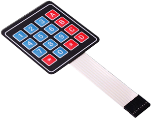
Matrix Keypad
Keypads are used in all types of devices, including cell phones, fax machines, microwaves, ovens, door locks, etc. They are practically everywhere. The tone of electronic devices uses them for user input.
In this section, we will discuss the logic and interface of a matrix keypad with a microcontroller to reduce the number of port pins required to read a certain number of digital inputs. The same logic applies to any matric keypad.
Why Matrix Keypad?
Typically, one digital input is connected to one port pin. When there are a lot of digital inputs that have to be read by the microcontroller, it requires the same number of port pins to read each input signal separately. It would not be feasible to allocate one pin for each of them, because these will occupy a lot of I/O pins. the main reason is that microcontrollers grow with the number of pins, and growth means more power, capabilities, and most of all higher prices. So in the end you can either get a cheap chip with little capabilities (that is what you need) but with few I/O pins, or a more powerful chip, which is much more than you need.
Therefore, a new interface technique will be needed to reduce the number of required pins in this kind of situation. The easiest way to do that is to arrange inputs in matrix form, which divides I/O pins into two sections: the rows and the columns. For example, a 64-key keyboard would require 64 digital input port pins. With a matrix circuit, 16 I/O pins arranged in 8 rows and 8 columns can connect 64 keys — 8 output pins to drive rows and 8 input pins to read columns.
What are the Key Matrices?
The Matrix Keypad is made by arranging push button switches in rows and columns. If you want to interface a 4 by 4 (16 keys) matrix keypad with a microcontroller. In a straightforward way, you will need 16 I/O pins of a microcontroller for that, but by using a simple technique we can reduce it to 8 I/O pins. In the matrix keypad, switches are connected in a special manner as shown in the figure below.
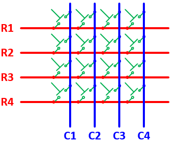
The blue lines are the columns and the red lines are the rows. There are 16 knots that the rows and columns intersect, and each knot connects one switch button. There will be no connections between columns and rows. When any of the switches are pressed, the corresponding columns and rows are connected (short-circuited), which can be detected by the microcontroller to identify which keys have been pressed.
How Does Key Matrix Work?
We make the columns as input pins and we drive the rows making their output pins. In order for the microcontroller to determine which button is pressed, it first needs to pull each of the four rows (R1 ~ R4) either logic low or high one at a time and then poll the states of the four columns (C1 ~ C4). Depending on the states of the columns, the microcontroller can detect which button is pressed.
Let us assume that a logic high signal is given to Row 2 (R2). If any of the keys belonging to Row 2 is pressed, the high signal from Row 2 will pass to the corresponding column as high. Watch the above animation, the button '5' is pressed, then column 2 will also be high as long as the button '5' is pressed. What this means is that if we know which row has currently logic high signal, and we watch the columns, then we can understand which button was pressed, if we detect power on a column. For example, our program pulls all four rows low and then pulls the second row (R2) high. It then reads the input states of each column and reads column 2 high. This means that a connection has been made between column 2 and row 2, so button '5' has been pressed.
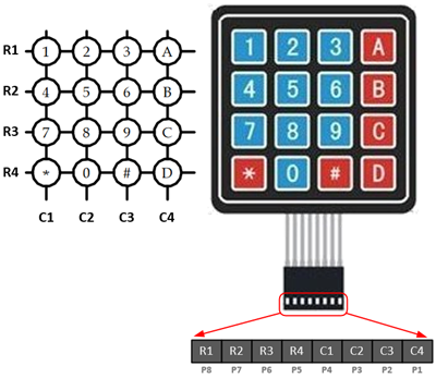
4x4 Matrix Keypad Pinout
Matrix keypads use a combination of four rows and four columns to provide button states to the host device, typically a microcontroller. Underneath each key is a pushbutton, with one end connected to one row, and the other end connected to one column. These connections are shown in Figure
Connection Diagram
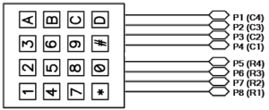
Keypad Connection for Open-Drain Output Pins
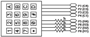
Keypad Connection with Resistors for Regular Output Pins
Required Components List
 |
4x4 Matrix Pad | × 1 |
 |
Character LCD module | × 1 |
| 10 KΩ Potentiometer | × 1 | |
| Breadboard | × 1 | |
| Breadboard Power Adapter | × 1 |
Circuit / Schematic Diagram
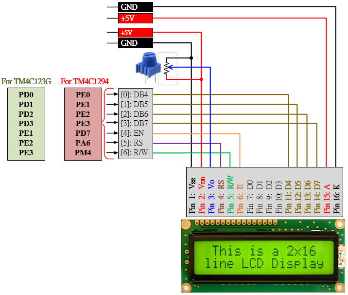
Connect the character LCD and matrix keypad to the Tiva LaunchPad board, as shown below. The pin directional need to be configured as follows:
- All the pins connected to the character LCD module are output directions.
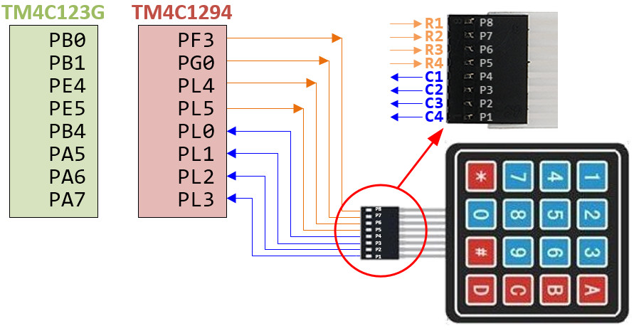
- The pins connected to the matrix keypad are divided into two parts: rows and columns. The pins connected to row wires are the output direction, and those connected to column wires are the input direction.
Required Reading Material
EK-TM4C123GXL LaunchPad
Pin configurations:
| Device | Port.Pin | Signal Type | PCTL | Direction | Drive Mode |
|---|---|---|---|---|---|
EK-TM4C1294XL LaunchPad
Pin configurations:
| Device | Port.Pin | Signal Type | PCTL | Direction | Drive Mode |
|---|---|---|---|---|---|
Procedure
- Create a new folder under the EE3450 folder and name it Lab05_Keypad. Then double-click the folder you just created to jump into it.
- Launch the Keil μVisio, and create a new project, save the project as Lab05_Keypad.
- Add the Common and ezTivaLIB folders to the include paths under the "Options for Target" setting.
- Add ezTiva LIB (ez123GLIB.lib or ez1294LIB.lib) into your project, and increase the stack and heap size under the "startup_TM4cXXX.s (Startup)" setting. ()
Configurations
GPIO Initialization and Configuration
GPIO Initialization Configuration
Next, we need to configure all the GPIO ports and pins that are used in the design.
According to the pin connections, complete the following GPIO configurations for each port. Fills the pin field by the value below:
- 0: Clean the bit
- 1: Set the bit
- x: Do not change the bit
- d: Do not care
For both TM4C123GXL and TM4C1294XL LaunchPads, the Port C [3:0] are used for JTAG/SWD. Therefore, when you configure Port C, you have to use bitwise operators to make sure your new configuration settings do not affect the JTAG/SWD function (PC3 ~ PC0).
Most of GPIO pins are configured as GPIOs and tri-stated by default (GPIOPCTL = 0, CPIOAFSEL = 0, GPIODIR = 0, GPIOPUR = 0, GPIOPDR = 0, GPIOODR = 0)
- Enable Clock to the GPIO Modules (RCGCGPIO register)
TM4C123G: SYSCTL->RCGCGPIO |= (_PORTs); |= binary = hex
8 4 2 1 8 4 2 1 7 6 5 4 3 2 1 0 bit Port F Port E Port D Port C Port B Port A port 0 0 -
TM4C1294: SYSCTL->RCGCGPIO |= (_PORTs); |= binary = hex
After enabling the clock signal, check the PRGPIO register until the corresponding bit is set to 1.8 4 2 1 8 4 2 1 8 4 2 1 8 4 2 1 15 14 13 12 11 10 9 8 7 6 5 4 3 2 1 0 bit Port Q Port P Port N Port M Port L Port K Port J Port H Port G Port F Port E Port D Port C Port B Port A port 0 - - -
In Assembly:
            LDR     R0, =SYSCTL_PRGPIO_R
Wait4GPIO   LDR     R1, [R0]
            TST     R1, #(__)
            BEQ     Wait4GPIO
In c:
while ( (SYSCTL->PRGPIO & ____ ) != ____ ) {}; - Unlock Port
TM4C123G: PD7 and PF0 are locked after reset.
TM4C1294: PD7 and PE7 are locked after reset
If those pins are used in the design, they must be unlocked first. To unlock the port, 0x4C4F434B must be written into the GPIOLOCK register and uncommit it by setting the GPIOCR register.
8 4 2 1 8 4 2 1 7 6 5 4 3 2 1 0 bit Port Pin 7 Pin 6 Pin 5 Pin 4 - Pin 3 Pin 2 Pin 1 Pin 0 pin Value in Hex Register Value to Register - - = ➤ GPIO ->LOCK = 0x4C4F434B - - = ➤ GPIO ->CR - - = ➤ GPIO ->LOCK = 0x4C4F434B - - = ➤ GPIO ->CR
Convert above configuration into registers
- GPIO Analog Mode Select
If any pin is used as an Analog signal (check Signal Type field on table 1), the appropriate bit in AMSEL must be set.
- 0: Digital signal
- 1: Analog signal
8 4 2 1 8 4 2 1 7 6 5 4 3 2 1 0 bit Port Pin 7 Pin 6 Pin 5 Pin 4 - Pin 3 Pin 2 Pin 1 Pin 0 pin Value in Hex Register Value to Register - - = ➤ GPIO ->AMSEL - - = ➤ GPIO ->AMSEL - - = ➤ GPIO ->AMSEL - - = ➤ GPIO ->AMSEL - - = ➤ GPIO ->AMSEL - - = ➤ GPIO ->AMSEL - - = ➤ GPIO ->AMSEL - GPIO Port Control (PCTL)
The PCTL register is used to select the specific peripheral signal for each GPIO pin when using the alternate function mode.
- 0: GPIO
- 1~0xF: Check the GPIO Pins and Alternate Function table
8421 8421 8421 8421 8421 8421 8421 8421 31~28 27~24 23~20 19~16 15~12 11~8 7~4 3~0 bit Port Pin 7 Pin 6 Pin 5 Pin 4 - Pin 3 Pin 2 Pin 1 Pin 0 pin Value in Hex Register Value to Register - - = ➤ GPIO ->PCTL - - = ➤ GPIO ->PCTL - - = ➤ GPIO ->PCTL - - = ➤ GPIO ->PCTL - - = ➤ GPIO ->PCTL - - = ➤ GPIO ->PCTL - - = ➤ GPIO ->PCTL - GPIO Alternate Function Select (AFSEL)
Setting a bit in the AFSEL register configures the corresponding GPIO pin to be controlled by PCTL peripheral function.
- 0: General I/O
- 1: Pin connected to the digital function defined in the PCTL register
8 4 2 1 8 4 2 1 7 6 5 4 3 2 1 0 bit Port Pin 7 Pin 6 Pin 5 Pin 4 - Pin 3 Pin 2 Pin 1 Pin 0 pin Value in Hex Register Value to Register - - = ➤ GPIO ->AFSEL - - = ➤ GPIO ->AFSEL - - = ➤ GPIO ->AFSEL - - = ➤ GPIO ->AFSEL - - = ➤ GPIO ->AFSEL - - = ➤ GPIO ->AFSEL - - = ➤ GPIO ->AFSEL - GPIO Pin Direction (DIR)
Set pin direction
- 0: Input pin
- 1: Output pin
8 4 2 1 8 4 2 1 7 6 5 4 3 2 1 0 bit Port Pin 7 Pin 6 Pin 5 Pin 4 - Pin 3 Pin 2 Pin 1 Pin 0 pin Value in Hex Register Value to Register - - = ➤ GPIO ->DIR - - = ➤ GPIO ->DIR - - = ➤ GPIO ->DIR - - = ➤ GPIO ->DIR - - = ➤ GPIO ->DIR - - = ➤ GPIO ->DIR - - = ➤ GPIO ->DIR - Internal Pull-Up Resistor (PUR), Pull-Down Resistor (PDR), and Open-Drain (ODR)
PUR: The pull-up control register
PDR: The pull-down control register
ODR: The open-drain control register
- 0: Disable
- 1: Enable
8 4 2 1 8 4 2 1 7 6 5 4 3 2 1 0 bit Port Pin 7 Pin 6 Pin 5 Pin 4 - Pin 3 Pin 2 Pin 1 Pin 0 pin Value in Hex Register Value to Register - - = ➤ GPIO -> - - = ➤ GPIO -> - - = ➤ GPIO -> - - = ➤ GPIO -> - - = ➤ GPIO -> - - = ➤ GPIO -> - - = ➤ GPIO -> - GPIO Digital Enable
Enables all the pins that are used in the design, including GPIO pins and alternate function pins.
- 0: Pin undriven
- 1: Enable pin
8 4 2 1 8 4 2 1 7 6 5 4 3 2 1 0 bit Port Pin 7 Pin 6 Pin 5 Pin 4 - Pin 3 Pin 2 Pin 1 Pin 0 pin Value in Hex Register Value to Register - - = ➤ GPIO ->DEN - - = ➤ GPIO ->DEN - - = ➤ GPIO ->DEN - - = ➤ GPIO ->DEN - - = ➤ GPIO ->DEN - - = ➤ GPIO ->DEN - - = ➤ GPIO ->DEN
Example Source Code
Copy the following example code to your main.c file.
Note: The example code is not yet complete, you must implement all functions following the lab instructions.
EK-TM4C123GXL LaunchPad
Keil C Sample Firmware Code
#include <stdio.h>
#include <stdlib.h>
#include <stdbool.h>
#include <stdint.h>

#include "TM4C123GH6PM.h"
#include "MyDefines.h"
#include "ez123G.h"

char ReadKeypad(void);
void Setup_GPIO(void);

int main(void)
{
    PEZOBJ_LCD  lcd;
    char        str[100];
    uint16_t    i = 0;
    char        ch;

    Setup_GPIO();

    lcd = ezLCD_Create();
    ezLCD_Connect_DataPort(lcd, _PORTD, _ON_PIN_3_0);
    ezLCD_Connect_ENPin(lcd, _PORTE, _PIN1);
    ezLCD_Connect_RSPin(lcd, _PORTE, _PIN2);
    ezLCD_Connect_RWPin(lcd, _PORTE, _PIN3);

    ezLCD_Start(lcd);
    ezLCD_ClearDisplay(lcd);
    ezLCD_Position(lcd, 1, 0);
    ezLCD_PrintString(lcd, "HELLO");

    while(1){
        ch = ReadKeypad();

        if (ch == '*') i *= 100;
        if (ch == '#') {
            i = 0;
            ezLCD_ClearDisplay(lcd);
        }
        if (ch >='0' && ch <= '9') i = i*10 + ch - '0';

        sprintf(str, "%d   ", i);
        ezLCD_Position(lcd, 0, 0);
        ezLCD_PrintString(lcd, str);

        ezDelay(100);
    }
}
//--------------------------------------------------------------
char Keypad[4][4]={         // Lookup Table for Keypad
    {'1','2','3','A'},
    {'4','5','6','B'},
    {'7','8','9','C'},
    {'*','0','#','D'}};

volatile uint32_t *R1 = (uint32_t *)GPIO? + (_PIN?);
volatile uint32_t *R2 = (uint32_t *)GPIO? + (_PIN?);
volatile uint32_t *R3 = (uint32_t *)GPIO? + (_PIN?);
volatile uint32_t *R4 = (uint32_t *)GPIO? + (_PIN?);
volatile uint32_t *C1 = (uint32_t *)GPIO? + (_PIN?);
volatile uint32_t *C2 = (uint32_t *)GPIO? + (_PIN?);
volatile uint32_t *C3 = (uint32_t *)GPIO? + (_PIN?);
volatile uint32_t *C4 = (uint32_t *)GPIO? + (_PIN?));

char ReadKeypad()
{
    int     row = 0;
    char    key = 0x00;

    // Code for Scanning Keypad

    return key;
}
//------------------------------------------------------------------------------
/*
Device      Port.Pins       DIR     DriveMode
LCD_RS
LCD_RW
LCD_E
LCD_D4
LCD_D5
LCD_D6
LCD_D7
R1
R2
R3
R4
C1
C2
C3
C4

Port ____
*/

void Setup_GPIO()
{
    // GPIO Initialization and Configuration
    // 1. Enable Clock to the GPIO Modules (SYSCTL->RCGCGPIO |= (_PORTs);)
    SYSCTL->RCGCGPIO |= (__);
    // allow time for clock to stabilize (SYSCTL->PRGPIO & (_PORTs))
    while ((SYSCTL->PRGPIO & (__)) != (__)) {};
    // 2. Unlock GPIO only PD7, PF0 on TM4C123G; PD7, PE7 on TM4C1294 (GPIOx->LOCK = 0x4C4F434B; and GPIOx->CR = _PINs;)
    // 3. Set Analog Mode Select bits for each Port (GPIOx->AMSEL = _PINs;  0=digital, 1=analog)
    // 4. Set Port Control Register for each Port (GPIOx->PCTL = PMCn << _PTCL_PINn, check the PCTL table)
    // 5. Set Alternate Function Select bits for each Port (GPIOx->AFSEL = _PINs;  0=regular I/O, 1=PCTL peripheral)
    // 6. Set Output pins for each Port (Direction of the Pins: GPIOx->DIR = _PINs; 0=input, 1=output)

    // 7. Set PUR bits (internal Pull-Up Resistor), PDR (Pull-Down Resistor), ODR (Open Drain) for each Port (0: disable, 1=enable)

    // 8. Set Digital ENable register on all port.pins (GPIOx->DEN = _PINs; 0=disable, 1=enable)

}
EK-TM4C1294XL LaunchPad
Keil C Sample Firmware Code
#include <stdio.h>
#include <stdlib.h>
#include <stdbool.h>
#include <stdint.h>

#include "TM4C1294NCPDT.h"
#include "MyDefines.h"
#include "ez1294.h"

char ReadKeypad(void);
void Setup_GPIO(void);

int main(void)
{
    PEZOBJ_LCD  lcd;
    char        str[100];
    uint16_t    i = 0;
    char        ch;

    Setup_GPIO();

    lcd = ezLCD_Create();
    ezLCD_Connect_DataPort(lcd, _PORTE, _ON_PIN_3_0);
    ezLCD_Connect_ENPin(lcd, _PORTD, _PIN7);
    ezLCD_Connect_RSPin(lcd, _PORTA, _PIN6);
    ezLCD_Connect_RWPin(lcd, _PORTM, _PIN4);

    ezLCD_Start(lcd);
    ezLCD_ClearDisplay(lcd);
    ezLCD_Position(lcd, 1,0);
    ezLCD_PrintString(lcd, "HELLO");

    while(1){
        ch = ReadKeypad();

        if (ch == '*') i *= 100;
        if (ch == '#') {
            i = 0;
            ezLCD_ClearDisplay(lcd);
        }
        if (ch >='0' && ch <= '9') i = i*10 + ch - '0';

        sprintf(str, "%d   ", i);
        ezLCD_Position(lcd, 0, 0);
        ezLCD_PrintString(lcd, str);

        ezDelay(100);
    }
}
//--------------------------------------------------------------
char Keypad[4][4]={         // Lookup Table for Keypad
    {'1','2','3','A'},
    {'4','5','6','B'},
    {'7','8','9','C'},
    {'*','0','#','D'}};

volatile uint32_t *R1 = (uint32_t *)GPIO? + (_PIN?);
volatile uint32_t *R2 = (uint32_t *)GPIO? + (_PIN?);
volatile uint32_t *R3 = (uint32_t *)GPIO? + (_PIN?);
volatile uint32_t *R4 = (uint32_t *)GPIO? + (_PIN?);
volatile uint32_t *C1 = (uint32_t *)GPIO? + (_PIN?);
volatile uint32_t *C2 = (uint32_t *)GPIO? + (_PIN?);
volatile uint32_t *C3 = (uint32_t *)GPIO? + (_PIN?);
volatile uint32_t *C4 = (uint32_t *)GPIO? + (_PIN?);

char ReadKeypad()
{
    int     row = 0;
    char    key = 0x00;

    // Code for Scanning Keypad

    return key;
}
//------------------------------------------------------------------------------
/*
Device      Port.Pins       DIR     DriveMode
LCD_RS
LCD_RW
LCD_E
LCD_D4
LCD_D5
LCD_D6
LCD_D7
R1
R2
R3
R4
C1
C2
C3
C4

Port ____
*/

void Setup_GPIO()
{
    // GPIO Initialization and Configuration
    // 1. Enable Clock to the GPIO Modules (SYSCTL->RCGCGPIO |= (_PORTs);)
    SYSCTL->RCGCGPIO |= (__);
    // allow time for clock to stabilize (SYSCTL->PRGPIO & (_PORTs))
    while ((SYSCTL->PRGPIO & (__)) != (__)) {};
    // 2. Unlock Port - PD7 & PF0 for TM4C123G ; PD7 & PE7 for TM4C1294
    GPIOD_AHB->LOCK = 0x4C4F434B;
    while( (GPIOD_AHB->LOCK & 0x01) == 0x01) {};
    *(((char*)GPIOD_AHB)+0x524) = 0x80;

    // 3. Set Analog Mode Select bits for each Port (GPIOx->AMSEL = _PINs;  0=digital, 1=analog)
    // 4. Set Port Control Register for each Port (GPIOx->PCTL = PMCn << _PTCL_PINn, check the PCTL table)
    // 5. Set Alternate Function Select bits for each Port (GPIOx->AFSEL = _PINs;  0=regular I/O, 1=PCTL peripheral)
    // 6. Set Output pins for each Port (Direction of the Pins: GPIOx->DIR = _PINs;  0=input, 1=output)

    // 7. Set PUR bits (internal Pull-Up Resistor), PDR (Pull-Down Resistor), ODR (Open Drain) for each Port (0: disable, 1=enable)

    // 8. Set Digital ENable register on all port.pins (GPIOx->DEN = _PINs; 0=disable, 1=enable)

}
Lab Experiments
Exp #5.1: Scan the Keypad
Inside the ReadKeypad() function, if no keys are pressed, it will return 0. If a key is pressed, it will return the ASCII value from the Keypad[] array that corresponds to that key. For example, if you press a key on the 3rd row, second column, the ReadKeypad() function will return the character '8' ( or ASCII code for '8').
Implement the following algorithm to "scan" the keypad in the ReadKeypad() function.
Scan Algorithm
- Drive row wire R1 low, and other rows high
- Read and test the states of all column wires (check the value of C1, C2, C3, and C4)
- If column Cn is low, it is shorted to row R1
- if column Cn is high, Cn is not shorted to any row wire & remains pulled high
- Repeat steps 1 & 2 but with different row wires driven low (and others high)
- A keypress is detected if a column line is detected in the low-state
- The key position is the intersection of that column and the row being driven low
- From the lookup table to get the ASCII code of the pressed key
- If no key is pressed, then the function should return null (zero value)
GPIO Addressing Mask
In this lab, you must use the GPIO addressing masks to access Row and Column pins. Please read Lesson 09: GPIO Ports and Configurations to get detailed information.
Timing Issue
There is a short delay from the time a pattern is written to an output port to the appearance of that pattern on the external pins. After writing a pattern to an output port (to drive row lines), insert a short program delay before reading the input port and testing the keypad column lines.
Example:
write to output port; // Row lines
ezDelayUs(10);
read input port; // Column lines
Pseudocode for ReadKeypad() Function
ReadKeypad(){
create variables: key = 0x00, row = 0x00
while-loop (row < 4)
set R1 output to 1
set R2 output to 1
set R3 output to 1
set R4 output to 1
if row equal to 0
set R1 output to 0
else if row equal to 1
set R2 output to 0
else if row equal to 2
set R3 output to 0
else if row equal to 3
set R4 output to 0
endif
Delay for 10us
if C1 equal to 0
set key from KeyPad array[row, 0]
else if C2 equal to 0
set key from KeyPad array[row, 1]
else if C3 equal to 0
set key from KeyPad array[row, 2]
else if C4 equal to 0
set key from KeyPad array[row, 3]
endif
if key not equal to 0
jump out while-loop
endif
increase row by 1
endwhile
return key value
}
Lab Questions
- Can you briefly describe your GPIO configuration for the matrix keypad? Explain what happens if the row pins are configured as general output pins without an open-drain function.
- What is the status of the column input if no key is pressed?
- In a 4 x 4 matrix keypad used in this lab, can we press two keys at the same time? Explain.
- In Exp #1, if you keep holding down a key, what happens to the system?
Exp #5.2: Detect Key Pressed
Now, modify your ReadKeypad() function to support key detection; when the user presses a key, the ASCII code is returned to the main code. If the same key is held, the function will return 0x00 unless the user releases the key or presses another key.
Hint:
Create a static variable preKey in the ReadKeypad() function to store the previous key value. Then compare it with the current key value; if the current key is the same as the previous, then return 0x00 to the main code.
(Don't forget to update the current key value to the preKey before you return the code.)
The pseudocode code is as follows:
ReadKeypad(){
create static variable: preKey = 0
put the original code for scanning and reading the keypad here
if key is not equal to preKey
set preKey equal to key
else
clear key to zero
endif
return with key
}