Tiva Lab 06: Stepper Motor Interface
Objective
- Learn how to interface a stepper motor with a microcontroller
- Learn how to drive a stepper motor
- Learn how to calculate the number of steps for the stepper motor to rotate at a certain angular degree
Required Reading Materials
Overview
In this Laboratory, you will write firmware for generating digital TTL signals that can be used to provide the stepping sequence for a four-phase unipolar stepper motor in full-step mode.
Stepper Motor: 28BYJ-48
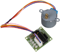
The 28BYJ-48 is a 5-wire unipolar stepper motor that runs on 5 volts. The detailed specs of the 28BYJ-48 stepper motor are shown below:
| Motor Type | Unipolar stepper motor |
| Connection Type | 5-wire connection (to the motor controller): Blue, Pink, Yellow, Orange, Red |
| Voltage | 5 Volts DC |
| Number of Phases | 4 |
| Operating Frequency (PPS) | 100Hz |
| Step Mode | Half-Step Mode: 8-step control signal sequence (recommended) Full-Step Mode: 4-step control signal sequence |
| Step Angle | Half-Step Mode: 5.625º per step / 64 steps per revolution of the internal motor shaft. Full-Step Mode: 11.25º per step / 32 steps per revolution of the internal motor shaft |
| Gear ratio | The manufacturer specifies: 64:1 Experimental result: 63.68395:1 Full revolution = steps per motor rotation x gear ratio For half-step: 64 steps per motor rotation x 63.68395 gear ratio ≒ 4076 steps per full revolution |
| Step Angle (1-2 phase) | 5.625º / 64 |
Step Sequence
The 28BYJ-48 is a Unipolar Stepper Motor. It has 4 coils of wire that are powered sequentially to make the magnetic motor shaft spin. When using the full-step method, 2 of the 4 coils are powered at each step. For the half-step mode, the first step is to power coil 1, then coil 1 and 2 together, then coil 2 only, and so on. With 4 coils, the half-step mode has 8 different signals. The following table shows the steps for half- and full-step modes.
WAVE DRIVE: 1-Phase at a Time (Full-Step)
| A IN4 |
B IN3 |
C IN2 |
D IN1 |
|
| Step 0 | X | |||
| Step 1 | X | |||
| Step 2 | X | |||
| Step 3 | X |
Simplest, but least used.
HALF STEP: 1 or 2 Phases at a Time (Half-Step)
| A IN4 |
B IN3 |
C IN2 |
D IN1 |
|
| Step 0 | X | |||
| Step 1 | X | X | ||
| Step 2 | X | |||
| Step 3 | X | X | ||
| Step 4 | X | |||
| Step 5 | X | X | ||
| Step 6 | X | |||
| Step 7 | X | X |
Smallest step angle. Medium torque.
FULL STEP: 2 Phases at a Time (Full-Step)
| A IN4 |
B IN3 |
C IN2 |
D IN1 |
|
| Step 0 | X | X | ||
| Step 1 | X | X | ||
| Step 2 | X | X | ||
| Step 3 | X | X |
Strongest torque.
In this lab, you need to complete the firmware code to control a stepper motor.
Required Component List
| Stepper Motor | x 1 | |
| ULN2003 Stepper Motor Driver Module | x 1 | |
| Breadboard Power Supply Module | x 1 | |
| Power Adapter 9V/2A | x 1 | |
| Breadboard | x 1 |
Circuit/Schematic Diagram
The stepper motor used in this lab is the 28BYJ-48, with gear reduction, hence providing relatively good torque but slow rotation. The ULN2003A is a Darlington high current transistor array used to drive the 5v stepper motor. The following diagrams are schematics of the internal coils of this stepper motor and how each coil connects to the ULN2003A for each Tiva LaunchPad board. These coils must be connected to the right output of the ULN2003A to ensure correct sequencing.
EK-TM4C123G LaunchPad - Circuit
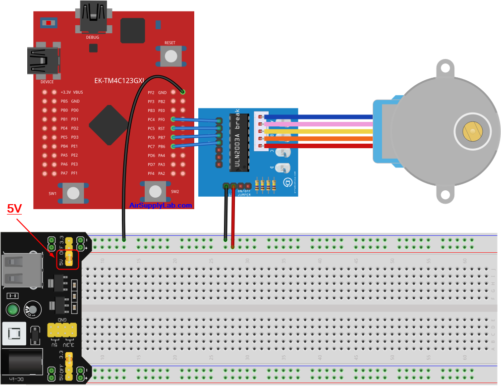
| Device | IN4 | IN3 | IN2 | IN1 |
| Port.Pin | PC7 | PC6 | PC5 | PC4 |
Pin Configurations
| Device | Port.Pin | Signal Type | PCTL | Direction | Drive Mode |
|---|---|---|---|---|---|
EK-TM4C1294XL LaunchPad - Circuit
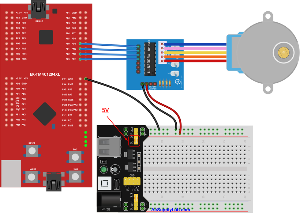
| Device | IN4 | IN3 | IN2 | IN1 |
| Port.Pin | PL3 | PL2 | PL1 | PL0 |
Pin Configurations
| Device | Port.Pin | Signal Type | PCTL | Direction | Drive Mode |
|---|---|---|---|---|---|
Procedure
- Create a new folder under the EE3450 folder and name it Lab06_StepperMotor.
- Launch the Keil μVisio and create a new project. Save the project to the project folder you just created in the previous step and set the project name to Lab06_StepperMotor.
- Add the Common folder to the include paths which is under the "Options for Target" setting.
Configurations
GPIO Initialization and Configuration
GPIO Initialization Configuration
Next, we need to configure all the GPIO ports and pins that are used in the design.
According to the pin connections, complete the following GPIO configurations for each port. Fills the pin field by the value below:
- 0: Clean the bit
- 1: Set the bit
- x: Do not change the bit
- d: Do not care
For both TM4C123GXL and TM4C1294XL LaunchPads, the Port C [3:0] are used for JTAG/SWD. Therefore, when you configure Port C, you have to use bitwise operators to make sure your new configuration settings do not affect the JTAG/SWD function (PC3 ~ PC0).
Most of GPIO pins are configured as GPIOs and tri-stated by default (GPIOPCTL = 0, CPIOAFSEL = 0, GPIODIR = 0, GPIOPUR = 0, GPIOPDR = 0, GPIOODR = 0)
- Enable Clock to the GPIO Modules (RCGCGPIO register)
TM4C123G: SYSCTL->RCGCGPIO |= (_PORTs); |= binary = hex
8 4 2 1 8 4 2 1 7 6 5 4 3 2 1 0 bit Port F Port E Port D Port C Port B Port A port 0 0 -
TM4C1294: SYSCTL->RCGCGPIO |= (_PORTs); |= binary = hex
After enabling the clock signal, check the PRGPIO register until the corresponding bit is set to 1.8 4 2 1 8 4 2 1 8 4 2 1 8 4 2 1 15 14 13 12 11 10 9 8 7 6 5 4 3 2 1 0 bit Port Q Port P Port N Port M Port L Port K Port J Port H Port G Port F Port E Port D Port C Port B Port A port 0 - - -
In Assembly:
            LDR     R0, =SYSCTL_PRGPIO_R
Wait4GPIO   LDR     R1, [R0]
            TST     R1, #(__)
            BEQ     Wait4GPIO
In c:
while ( (SYSCTL->PRGPIO & ____ ) != ____ ) {}; - Unlock Port
TM4C123G: PD7 and PF0 are locked after reset.
TM4C1294: PD7 and PE7 are locked after reset
If those pins are used in the design, they must be unlocked first. To unlock the port, 0x4C4F434B must be written into the GPIOLOCK register and uncommit it by setting the GPIOCR register.
8 4 2 1 8 4 2 1 7 6 5 4 3 2 1 0 bit Port Pin 7 Pin 6 Pin 5 Pin 4 - Pin 3 Pin 2 Pin 1 Pin 0 pin Value in Hex Register Value to Register - - = ➤ GPIO ->LOCK = 0x4C4F434B - - = ➤ GPIO ->CR - - = ➤ GPIO ->LOCK = 0x4C4F434B - - = ➤ GPIO ->CR
Convert above configuration into registers
- GPIO Analog Mode Select
If any pin is used as an Analog signal (check Signal Type field on table 1), the appropriate bit in AMSEL must be set.
- 0: Digital signal
- 1: Analog signal
8 4 2 1 8 4 2 1 7 6 5 4 3 2 1 0 bit Port Pin 7 Pin 6 Pin 5 Pin 4 - Pin 3 Pin 2 Pin 1 Pin 0 pin Value in Hex Register Value to Register - - = ➤ GPIO ->AMSEL - - = ➤ GPIO ->AMSEL - - = ➤ GPIO ->AMSEL - - = ➤ GPIO ->AMSEL - - = ➤ GPIO ->AMSEL - - = ➤ GPIO ->AMSEL - - = ➤ GPIO ->AMSEL - GPIO Port Control (PCTL)
The PCTL register is used to select the specific peripheral signal for each GPIO pin when using the alternate function mode.
- 0: GPIO
- 1~0xF: Check the GPIO Pins and Alternate Function table
8421 8421 8421 8421 8421 8421 8421 8421 31~28 27~24 23~20 19~16 15~12 11~8 7~4 3~0 bit Port Pin 7 Pin 6 Pin 5 Pin 4 - Pin 3 Pin 2 Pin 1 Pin 0 pin Value in Hex Register Value to Register - - = ➤ GPIO ->PCTL - - = ➤ GPIO ->PCTL - - = ➤ GPIO ->PCTL - - = ➤ GPIO ->PCTL - - = ➤ GPIO ->PCTL - - = ➤ GPIO ->PCTL - - = ➤ GPIO ->PCTL - GPIO Alternate Function Select (AFSEL)
Setting a bit in the AFSEL register configures the corresponding GPIO pin to be controlled by PCTL peripheral function.
- 0: General I/O
- 1: Pin connected to the digital function defined in the PCTL register
8 4 2 1 8 4 2 1 7 6 5 4 3 2 1 0 bit Port Pin 7 Pin 6 Pin 5 Pin 4 - Pin 3 Pin 2 Pin 1 Pin 0 pin Value in Hex Register Value to Register - - = ➤ GPIO ->AFSEL - - = ➤ GPIO ->AFSEL - - = ➤ GPIO ->AFSEL - - = ➤ GPIO ->AFSEL - - = ➤ GPIO ->AFSEL - - = ➤ GPIO ->AFSEL - - = ➤ GPIO ->AFSEL - GPIO Pin Direction (DIR)
Set pin direction
- 0: Input pin
- 1: Output pin
8 4 2 1 8 4 2 1 7 6 5 4 3 2 1 0 bit Port Pin 7 Pin 6 Pin 5 Pin 4 - Pin 3 Pin 2 Pin 1 Pin 0 pin Value in Hex Register Value to Register - - = ➤ GPIO ->DIR - - = ➤ GPIO ->DIR - - = ➤ GPIO ->DIR - - = ➤ GPIO ->DIR - - = ➤ GPIO ->DIR - - = ➤ GPIO ->DIR - - = ➤ GPIO ->DIR - Internal Pull-Up Resistor (PUR), Pull-Down Resistor (PDR), and Open-Drain (ODR)
PUR: The pull-up control register
PDR: The pull-down control register
ODR: The open-drain control register
- 0: Disable
- 1: Enable
8 4 2 1 8 4 2 1 7 6 5 4 3 2 1 0 bit Port Pin 7 Pin 6 Pin 5 Pin 4 - Pin 3 Pin 2 Pin 1 Pin 0 pin Value in Hex Register Value to Register - - = ➤ GPIO -> - - = ➤ GPIO -> - - = ➤ GPIO -> - - = ➤ GPIO -> - - = ➤ GPIO -> - - = ➤ GPIO -> - - = ➤ GPIO -> - GPIO Digital Enable
Enables all the pins that are used in the design, including GPIO pins and alternate function pins.
- 0: Pin undriven
- 1: Enable pin
8 4 2 1 8 4 2 1 7 6 5 4 3 2 1 0 bit Port Pin 7 Pin 6 Pin 5 Pin 4 - Pin 3 Pin 2 Pin 1 Pin 0 pin Value in Hex Register Value to Register - - = ➤ GPIO ->DEN - - = ➤ GPIO ->DEN - - = ➤ GPIO ->DEN - - = ➤ GPIO ->DEN - - = ➤ GPIO ->DEN - - = ➤ GPIO ->DEN - - = ➤ GPIO ->DEN
Example Source Code
EK-TM4C123GXL LaunchPad - main.c
#include <stdio.h>
#include <stdlib.h>
#include <stdint.h>
#include <stdbool.h>

#include "TM4C123GH6PM.h"
#include "MyDefines.h"
#include "ez123G.h"

void Setup_GPIO(void);

#define CW    0
#define CCW   1
void StepperMotor(int s, bool direction);
volatile uint32_t *Stepper = (uint32_t *)GPIO? + (_PIN? | .... );

//------------------------------------------------------------------------------
int main()
{
    int i = 0;

    Setup_GPIO();
    *Stepper = ____; // Step 0 value

    while(1){
        // If users press SW1, rotate CW for 5 steps

		// If users press SW2, rotate CCW for 5 steps

        DelayMs(200);
    }
}
//------------------------------------------------------------------------------
void Setup_GPIO(void)
{
    // GPIO Initialization and Configuration
    // 1. Enable Clock to the GPIO Modules (SYSCTL->RCGCGPIO |= (_PORTs);)
    SYSCTL->RCGCGPIO |= (__);
    // allow time for clock to stabilize (SYSCTL->PRGPIO)
    while ((SYSCTL->PRGPIO & (__) ) != (__) ){};
    // 2. Unlock GPIO only PD7, PF0 on TM4C123G; PD7, PE7 on TM4C1294 (GPIOx->LOCK = 0x4C4F434B; and GPIOx->CR = _PINs;)
    GPIOF->LOCK = 0x4C4F434B;   // Unlock for GPIOF
    GPIOF->CR |= _PIN0;         // Commit for PIN0
    GPIOF->LOCK = 0;
    // 3. Set Analog Mode Select bits for each Port (GPIOx->AMSEL = _PINs; 0=digital, 1=analog)
    // 4. Set Port Control Register for each Port (GPIOx->PCTL = PMCn << _PTCL_PINn, check the PCTL table)
    // 5. Set Alternate Function Select bits for each Port (GPIOx->AFSEL = _PINs; 0=regular I/O, 1=PCTL peripheral)
    // 6. Set Output pins for each Port (Direction of the Pins: GPIOx->DIR = _PINs; 0=input, 1=output)

    // 7. Set PUR bits for internal pull-up, PDR for pull-down reg, ODR for open drain (0: disable, 1=enable)

    // 8. Set Digital ENable register on all port.pins (GPIOx->DEN = _PINs; 0=disable, 1=enable)

}
//------------------------------------------------------------------------------
void StepperMotor(int s, bool direction)
{
    int i;

}
//------------------------------------------------------------------------------
EK-TM4C1294XL LaunchPad - main.c
#include <stdio.h>
#include <stdlib.h>
#include <stdint.h>
#include <stdbool.h>

#include <TM4C1294NCPDT.h>
#include "MyDefines.h"
#include "ez1294.h"

void Setup_GPIO(void);

#define CW    0
#define CCW   1
void StepperMotor(int s, bool direction);
volatile uint32_t *Stepper = (uint32_t *)GPIO? + (_PIN? | .... );

//------------------------------------------------------------------------------
int main()
{
    int i = 0;

    Setup_GPIO();
    *Stepper = ____; // Step 0 value

    while(1){
        // If users press SW1, rotate CW for 5 steps

		// If users press SW2, rotate CCW for 5 steps

        DelayMs(200);
    }
}
//------------------------------------------------------------------------------
void Setup_GPIO(void)
{
    // GPIO Initialization and Configuration
    // 1. Enable Clock to the GPIO Modules (SYSCTL->RCGCGPIO |= (_PORTs);)
    SYSCTL->RCGCGPIO |= (__);
    // allow time for clock to stabilize (SYSCTL->PRGPIO)
    while ((SYSCTL->PRGPIO & (__) ) != (__) ){};
    // 2. Unlock GPIO only PD7, PF0 on TM4C123G; PD7, PE7 on TM4C1294 (GPIOx->LOCK = 0x4C4F434B; and GPIOx->CR = _PINs;)
    // 3. Set Analog Mode Select bits for each Port (GPIOx->AMSEL = _PINs; 0=digital, 1=analog)
    // 4. Set Port Control Register for each Port (GPIOx->PCTL = PMCn << _PTCL_PINn, check the PCTL table)
    // 5. Set Alternate Function Select bits for each Port (GPIOx->AFSEL = _PINs; 0=regular I/O, 1=PCTL peripheral)
    // 6. Set Output pins for each Port (Direction of the Pins: GPIOx->DIR = _PINs; 0=input, 1=output)

    // 7. Set PUR bits for internal pull-up, PDR for pull-down reg, ODR for open drain (0: disable, 1=enable)

    // 8. Set Digital ENable register on all port.pins (GPIOx->DEN = _PINs; 0=disable, 1=enable)

}
//------------------------------------------------------------------------------
void StepperMotor(int s, bool direction)
{
    int i;

}
//------------------------------------------------------------------------------
Lab Experiments
Write a firmware code to control the stepper motor rotation:
- When SW1 and SW2 are pressed simultaneously, the stepper motor rotates 90 degrees clockwise
- When SW1 is pressed, the stepper motor rotates 5 steps clockwise (CW)
- When SW2 is pressed, the stepper motor rotates 5 steps counterclockwise (CCW)
You will have to calculate the number of steps required to rotate 90 degrees from the stepper motor data sheet at the top of this lab.
There are three ways to implement the stepper motor control:
Exp#6.1: Array
Since the pins used for the stepper motor are assigned in the same port, the output values for the stepper motor can be stored in a one-dimensional array. To control the stepper motor's rotation and direction, read the values from the array in sequence and send them to the port.
The template and pseudocode for Stepper() function as below:
uint8_t   Steps1[] = {0x__, 0x__, 0x__, 0x__ };      // WAVE DRIVE: 1-Phase at a Time (Full-Step)

void StepperMotor(int s, bool direction)
{
    int i;

    // Implement the pPseudocode here

}
create variable: i
crease static variable: idx = 0
set i to 0
while-loop (i < s):
if direction equal to CW
increase idx by 1
else
decrease idx by 1
endif
// Check idx range
if idx less than 0
set idx to the array size - 1
else if idx greater than or equal to the array size
clear idx to 0
endif
set *Stepper to Steps1[idx] value
increase i by 1
delay for 10 ms
endwhile
Exp#6.2: State Machine
The mealy state machine can be used in this case. If the current state is in S_1 and the direction is CW, then the state translates to S_2 and sets the Stepper to step2 value. The state diagram is shown in Figure 2-1.
Note: In the main() function, the new initial value must be assigned to *Stepper in lin 24.
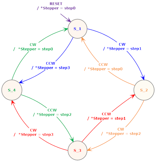
Figure 2-1: The Mealy State Diagram for Stepper Motor
Template code for state machine as below:
typedef enum STATES{
    S_1,
    S_2,
    S_3,
    S_4
} STATES;

uint8_t Steps2[] = {0x__, 0x__, 0x__, 0x__ }; // The array values of FULL STEP: 2 Phases at a Time (Full-Step)

void StepperMotor(int s, bool direction)
{
    int i;
    static STATES state = S_1;

    for (i = 0; i< s; i++){
        switch( state ) {
            case S_1:
                if (direction == CW){
                    state = ____;
                    *Stepper = ____;
                } else {

                }
            break;
            case S_2:

            break;
            case S_3:

            break;
            case S_4:

            break;
        }
        DelayMs(10);
    }
}
Exp#6.3: Double-Linked List
Now, use the Double-Linked List to implement the Stepper() function by using the Half step (using the "2-phase at a time" table).
Note: In the main() function, the new initial value must be assigned to *Stepper in lin 24. The number of steps for 120 degrees must be recalculated, and write the value in lines 27 and 30.
//------------------------------------------------------------------------------
int main()
{
    int i = 0;

    Setup_GPIO();
    *Stepper = ____; // Step 0 value

    while(1){
        for (i = 0; i < ____; i++)  // (steps for 120 degree) / 5
            StepperMotor(5, CW);
        DelayMs(500);
        for (i = 0; i < ____; i++)  // (steps for 120 degree) / 5
            StepperMotor(5, CCW);
        DelayMs(500);
    }
}
//------------------------------------------------------------------------------
The template and pseudocode for Stepper() function as below:
typedef struct STEPS{
    struct STEPS    *pre;
    uint8_t         data;
    struct STEPS    *next;
} STEPS;

STEPS Steps3[]={
    {_, _, _},      // Steps3[0] ==> {preLink, data, nextLink}
    {_, _, _},      // Steps3[1]
    {_, _, _},      // Steps3[2]
    {_, _, _},      // Steps3[3]
    {_, _, _},      // Steps3[4]
    {_, _, _},      // Steps3[5]
    {_, _, _},      // Steps3[6]
    {_, _, _}       // Steps3[7]
};

void StepperMotor(int s, bool direction)
{
    int             i;
    static STEPS*   p = Steps3;

    // Implement the Pseudocode here

}
clear i to 0
while-loop(i < s)
if direction equal to CW
set p to next link
else
set p to previous link
endif
set *Stepper to the data in the link
increase i by 1
delay for 10 ms
endwhile
Questions
- A 10° per step stepper motor is given 60 steps clockwise (CW) and 15 steps counter-clockwise (CCW). Assuming it started at 0°, calculate the final position in degrees.