Page 33 - EE2449_TTL_Datasheet
P. 33

SN54/74LS151


             LOGIC DIAGRAM
                                                      I 0   I 1  I 2   I 3  I 4   I 5   I 6  I 7
                                   9                    4     3    2     1    15    14   13    12
                               S 2
                                  10
                               S 1
                                  11
                               S 0
                                   7
                                E


                             V CC  = PIN 16
                             GND = PIN 8                                  6  5
                                = PIN NUMBERS
                                                                        Z  Z


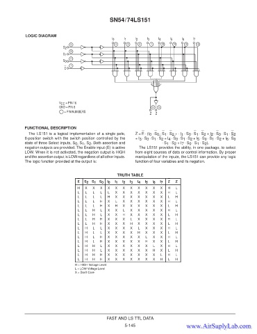
             FUNCTIONAL DESCRIPTION
               The LS151 is a logical implementation of a single pole,  Z = E ⋅ (I 0  ⋅ S 0  ⋅ S 1  ⋅ S 2  + ⋅ I 1  ⋅ S 0  ⋅ S 1  ⋅ S 2  + I 2  ⋅ S 0  ⋅ S 1  ⋅ S 2
             8-position switch with the switch position controlled by the  + I 3  ⋅ S 0  ⋅ S 1  ⋅ S 2  + I 4  ⋅ S 0  ⋅ S 1  ⋅ S 2  + I 5  ⋅ S 0  ⋅ S 1  ⋅ S 2  + I 6  ⋅ S 0
             state of three Select inputs, S 0 , S 1 , S 2 . Both assertion and  ⋅ S 1  ⋅ S 2  + I 7  ⋅ S 0  ⋅ S 1  ⋅ S 2 ).
             negation outputs are provided. The Enable input (E) is active  The LS151 provides the ability, in one package, to select
             LOW. When it is not activated, the negation output is HIGH  from eight sources of data or control information. By proper
             and the assertion output is LOW regardless of all other inputs.  manipulation of the inputs, the LS151 can provide any logic
             The logic function provided at the output is:       function of four variables and its negation.


                                                         TRUTH TABLE
                                      E  S 2  S 1  S 0  I 0  I 1  I 2  I 3  I 4  I 5  I 6  I 7  Z  Z
                                      H   X  X   X  X   X  X   X   X  X   X  X   H   L
                                      L   L  L   L  L   X  X   X   X  X   X  X   H   L
                                      L   L  L   L  H   X  X   X   X  X   X  X   L   H
                                      L   L  L   H  X   L  X   X   X  X   X  X   H   L
                                      L   L  L   H  X   H  X   X   X  X   X  X   L   H
                                      L   L  H   L  X   X   L  X   X  X   X  X   H   L
                                      L   L  H   L  X   X  H   X   X  X   X  X   L   H
                                      L   L  H   H  X   X  X   L   X  X   X  X   H   L
                                      L   L  H   H  X   X  X   H   X  X   X  X   L   H
                                      L  H   L   L  X   X  X   X   L  X   X  X   H   L
                                      L  H   L   L  X   X  X   X   H  X   X  X   L   H
                                      L  H   L   H  X   X  X   X   X  L   X  X   H   L
                                      L  H   L   H  X   X  X   X   X  H   X  X   L   H
                                      L  H   H   L  X   X  X   X   X  X   L  X   H   L
                                      L  H   H   L  X   X  X   X   X  X   H  X   L   H
                                      L  H   H   H  X   X  X   X   X  X   X  L   H   L
                                      L  H   H   H  X   X  X   X   X  X   X  H   L   H
                                     H = HIGH Voltage Level
                                     L = LOW Voltage Level
                                     X = Don’t Care


                                                    FAST AND LS TTL DATA
                                                            5-145
                                                                                          www.AirSuplyLab.com
                                                                                          www.AirSuplyLab.com
   28   29   30   31   32   33   34   35   36   37   38